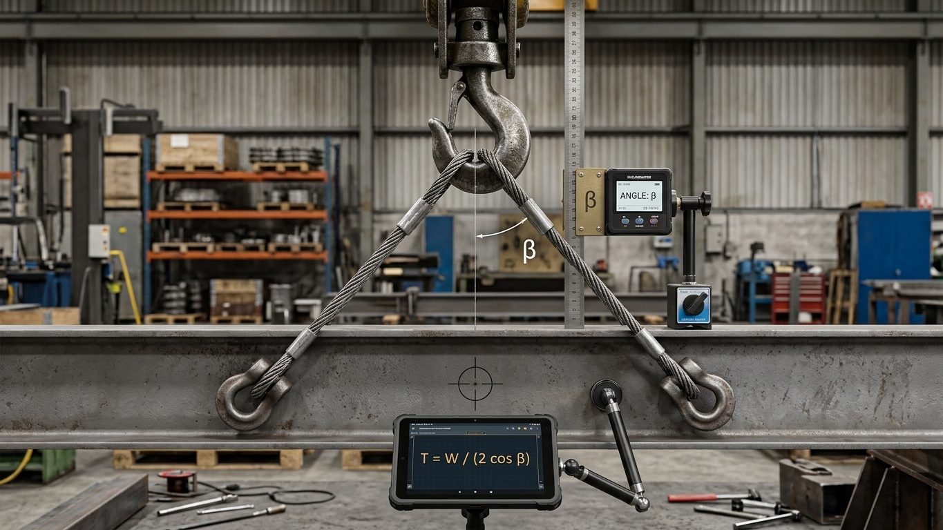
The simple formula T = W ÷ (2 cos β) only applies when both legs are the same length, at the same angle and the CoG is midway between the lift points. In practice the CoG is often off-centre. The hook must then sit above the CoG, so the two legs take up different angles and carry different loads. The leg nearer the CoG is steeper and shorter, and it carries more.
The method
With the hook directly above the CoG, the two leg tensions and the weight are three forces meeting at the hook. They must balance in both directions:
- The horizontal components of the two legs are equal and opposite: H₁ = H₂ = H.
- The vertical components add up to the weight: V₁ + V₂ = W.
Let a and b be the horizontal distances from the CoG to lift points 1 and 2, and h₁ and h₂ the vertical distances from the hook down to each lift point. Then:
H = W ÷ (h₁/a + h₂/b) V₁ = H × h₁/a V₂ = H × h₂/b T = √(V² + H²)
When both lift points are at the same height (h₁ = h₂ = h), this reduces to the familiar lever rule: V₁ = W × b ÷ (a + b) and V₂ = W × a ÷ (a + b), and each tension is T = V × L ÷ h, where L is that leg’s length from hook to lift point.
Example 1: lift points at the same height
A 20 t load (including rigging below the hook). The CoG is 1.5 m from lift point 1 and 2.5 m from lift point 2. The hook is 3.0 m above the lift points.
- V₁ = 20 × 2.5 ÷ 4.0 = 12.5 t; V₂ = 20 × 1.5 ÷ 4.0 = 7.5 t
- Leg 1 length = √(1.5² + 3.0²) = 3.354 m, at 26.6° from vertical; leg 2 = √(2.5² + 3.0²) = 3.905 m, at 39.8°.
- T₁ = 12.5 × 3.354 ÷ 3.0 = 13.98 t; T₂ = 7.5 × 3.905 ÷ 3.0 = 9.76 t
- Check: H₁ = 12.5 × 1.5 ÷ 3.0 = 6.25 t and H₂ = 7.5 × 2.5 ÷ 3.0 = 6.25 t. They are equal, as they must be.
Had the load been treated as symmetrical, each leg would have been sized for about 11 t. Leg 1 actually carries 14 t, about 25% more.
Example 2: lift point 1 is 0.5 m higher
Same load and plan distances, but lift point 1 is on a raised lug, so h₁ = 2.5 m and h₂ = 3.0 m.
- H = 20 ÷ (2.5/1.5 + 3.0/2.5) = 20 ÷ 2.867 = 6.98 t
- V₁ = 6.98 × 2.5/1.5 = 11.63 t; V₂ = 6.98 × 3.0/2.5 = 8.37 t
- T₁ = √(11.63² + 6.98²) = 13.56 t; T₂ = √(8.37² + 6.98²) = 10.90 t
Changing the lug height changed how the load divides between the legs, even though the CoG did not move. This is why the lever rule must not be used when lift points are at different elevations.
Practical points
- Leg lengths decide the geometry. For the load to hang level with the hook above the CoG, each leg must be cut (or adjusted) to its calculated length. Equal legs on an off-centre CoG make the load tilt.
- Size every component for its own leg. Use the larger tension for the sling, shackle and lug on that side, not the average.
- Keep both legs within 60° of vertical. In Example 1 the flatter leg is at 39.8°.
- Marked WLL of a two-leg sling assembly (EN 13414-1 / EN 818-4 uniform load method) assumes symmetrical loading. With an offset CoG, check each leg against its single-leg WLL instead of relying on the assembly rating.
Choosing sling lengths for a level lift
When the load must hang level, work backwards from the geometry. Decide the hook height h above the lift points, which sets the leg angles, then calculate each leg length so the hook sits exactly above the CoG:
L₁ = √(a² + h₁²) L₂ = √(b² + h₂²) measured from the hook (or master link) bearing point to the lift point bearing point, including shackles.
A common limit is that no leg should be more than 45° from vertical (60° is the absolute maximum for most marked ratings). The longest horizontal distance controls, so for a leg angle of β or less on the far leg you need h ≥ b ÷ tan β.
Example. The 20 t load from Example 1 (a = 1.5 m, b = 2.5 m, lift points at the same level). For β ≤ 45°, h ≥ 2.5 ÷ tan 45° = 2.5 m. With h = 2.5 m:
- L₁ = √(1.5² + 2.5²) = 2.915 m; L₂ = √(2.5² + 2.5²) = 3.536 m.
- Vertical shares are unchanged by the hook height: V₁ = 12.5 t, V₂ = 7.5 t.
- T₁ = 12.5 × 2.915 ÷ 2.5 = 14.58 t; T₂ = 7.5 × 3.536 ÷ 2.5 = 10.61 t.
Compare Example 1, where the hook was 3.0 m above the lift points and T₁ was 13.98 t. Lowering the hook by 0.5 m raised the heaviest leg tension by about 4%, and the far leg by more. Shorter rigging always means flatter legs and higher tensions; it also means less headroom needed, which is often why it is chosen. Make the trade deliberately.
Leg lengths in practice come in standard sizes. Make up the difference with shackles, links or a chain block in the long leg, and recalculate with the lengths you actually have. A difference of a few centimetres in a short leg can tilt the load noticeably.
What happens with equal legs on an offset CoG
If equal-length slings are used when the CoG is not midway between the lift points, the hook cannot stay at the midpoint. As the load leaves the ground it swings and tilts until the CoG is under the hook. The near leg becomes steeper and carries more; the far leg flattens.
Example. Two 3.5 m slings to lift points 4.0 m apart; CoG 1.5 m from lift point 1 and 0.3 m below the line of the lift points; load 20 t. With both legs equal, the hook starts 2.87 m above the middle of the lift points. The load rotates by about 9.0° (lift point 2 rises about 0.6 m) until the CoG is plumb below the hook. The legs then sit at 25.9° and 43.8° from vertical, carrying T₁ = 14.76 t and T₂ = 9.31 t.
Two lessons follow. First, the leg nearer the CoG is the one to size; designing for an even split (here 11.5 t per leg) would under-rate it by about 22%. Second, the tilt itself may be unacceptable: equipment with liquids, glazing, or fragile internals; a load that has to enter an opening; or a load whose tilt shifts the CoG further. The cure is unequal legs or an adjustable leg, not a hopeful lift.
Sling angle and the horizontal force on the load
Whenever a leg is not vertical, its tension has a horizontal component H that pulls the lift points towards each other. In a two-leg bridle H is the same in both legs. For Example 1, H = V₁ × a ÷ h₁ = 12.5 × 1.5 ÷ 3.0 = 6.25 t. This compresses the load between the lift points and loads each lift point sideways if the lug is not aligned with the sling.
- A long, slender load (a pipe, a beam, a column, a thin-walled tank) can buckle or bend under that compression. Check it, or use a spreader to take the horizontal force out of the load (Chapter 6).
- Plate lugs must be in the plane of the sling. A lug loaded across its thickness is much weaker than in its plane (Chapter 5).
- Eyebolts and swivel hoist rings have reduced ratings at an angle; some are not rated for angled pulls at all.
| Leg angle from vertical β | Tension factor 1 ÷ cos β | Horizontal factor tan β |
|---|---|---|
| 0° | 1.000 | 0.000 |
| 15° | 1.035 | 0.268 |
| 30° | 1.155 | 0.577 |
| 45° | 1.414 | 1.000 |
| 60° | 2.000 | 1.732 |
Multiply each leg’s vertical share by these factors to get the leg tension and the horizontal force. Note which angle convention a table uses: some quote the angle from horizontal, in which case 30° from horizontal is the same as 60° from vertical, and the tension factor is 2.0, not 1.155.
Adjusting the bridle on site
Chain blocks, lever hoists or adjustable shortening clutches in one leg let the rigger level the load at the trial lift. Remember three things:
- In a two-leg bridle, adjusting a leg changes the tilt of the load and the leg angles; it does not make the leg nearer the CoG carry less. The vertical shares are set by where the CoG is.
- The adjuster becomes part of the leg. Its rated load must cover the full leg tension, and its own length must be included in the geometry.
- Adjust with the load landed or just clear of its supports, never with people under or beside it.
From leg tension to a sling you can order
Marked ratings on multi-leg slings are worked out for symmetrical loading. Under the uniform load method used in EN 13414-1 and EN 818-4, a two-leg sling is marked at 1.4 × the single-leg WLL for leg angles 0–45° from vertical and 1.0 × for 45–60°. That 1.4 is simply 2 × cos 45°: it assumes both legs share equally at the worst angle in the band.
For an offset CoG, ignore the marked bridle rating and work from the single-leg WLL:
- Find the heaviest leg tension from the geometry (Example 1: T₁ = 13.98 t).
- The single-leg WLL must be at least that tension: 13.98 t or more.
- A two-leg sling marked 20 t (0–45°) has a single-leg WLL of 20 ÷ 1.4 = 14.3 t. It is just adequate for leg 1, with almost no margin for a heavier CoG estimate.
- If the weight or CoG is only calculated, choose the next size up, or recheck with load cells at the trial lift.
The same check applies to every other item in the leg: the shackle at the lift point, the lug itself, the master link and the hook. Each must carry the heaviest leg tension at the angle it sees, not half the load.
Common mistakes
- Using T = W ÷ (2 cos β) when the CoG is off-centre. It underestimates the heavier leg.
- Measuring the leg angle from the wrong reference (horizontal versus vertical).
- Measuring leg length to the sling eye instead of to the bearing point of the shackle or hook.
- Ignoring the 0.5 m height difference between lift points on a stepped skid or a vessel with lugs on different courses.
- Ignoring the horizontal force and lifting a long, thin load from its ends with a short bridle.
- Choosing slings by the marked two-leg rating (which assumes equal sharing at a set angle) without checking the actual heavier leg.
Field checklist
- CoG position relative to both lift points known in plan and height; lift point heights known.
- Leg lengths calculated so the hook is above the CoG, including shackles and links.
- Heaviest leg tension calculated; each leg’s rated load (single-leg vertical WLL × any hitch factor) is at least that tension.
- No leg flatter than the limit set in the lift plan (typically 45° from vertical, never more than 60°).
- Horizontal force checked against the load’s strength and the lift points’ side-load capacity.
- Trial lift: raise a short distance, check level and leg tensions (load cells if fitted), adjust, then continue.
Self-check questions
1. A 16 t load has its CoG 1.0 m from lift point 1 and 3.0 m from lift point 2, both at the same height. What are the vertical shares?
V₁ = 16 × 3.0 ÷ 4.0 = 12 t; V₂ = 16 × 1.0 ÷ 4.0 = 4 t. Three quarters of the load is on the near leg.
2. For question 1 with the hook 3.0 m above the lift points, what are the leg lengths and tensions?
L₁ = √(1.0² + 3.0²) = 3.162 m; L₂ = √(3.0² + 3.0²) = 4.243 m. T₁ = 12 × 3.162 ÷ 3.0 = 12.65 t; T₂ = 4 × 4.243 ÷ 3.0 = 5.66 t.
3. What is the horizontal force between the lift points in question 2?
H = V₁ × a ÷ h = 12 × 1.0 ÷ 3.0 = 4.0 t (the same from leg 2: 4 × 3.0 ÷ 3.0 = 4.0 t).
4. Why does adjusting one leg of a two-leg bridle not change the vertical load share much?
For lift points at the same level, the vertical shares come from moment balance about the CoG and depend only on the horizontal distances a and b. Shortening a leg tilts the load and changes the angles, which changes a and b only slightly.
5. A table gives a leg angle of 60°. What tension factor applies?
It depends on the reference. If 60° is from horizontal, the leg is 30° from vertical and the factor is 1.155. If 60° is from vertical, the factor is 2.0. Always check the convention.
General guidance only. It does not replace the manufacturer's data, the applicable standards or the judgement of a competent person.
References
Technical references consulted for this chapter. The text and worked examples are original to LiftPlan Pro.
- J. Keith Anderson, Rigging Engineering Calculations (Industrial Training International).
- Rigging Handbook, 2nd edition (Bechtel Equipment Operations, 2002).
- BS EN 13414-1 (wire rope slings), BS EN 818-4 (chain slings), BS EN 1492-1/-2 (textile slings).
All 18 chapters
- Load weight and centre of gravity: the two numbers every lift depends on
- Two-leg bridles: unequal legs, offset centre of gravity and lift points at different heights
- Three- and four-leg bridles: how the load really shares between the legs
- Sling selection: sling types, choke and basket hitches, and the D/d ratio
- Rigging hardware: shackles, hooks, eyebolts and wire rope terminations
- Spreader bars and lifting beams: forces, stability and design basis
- Mobile crane capacity: reading the chart, net load, utilisation and reeving
- Outrigger loads and crane mats: from crane reactions to ground pressure
- Tandem lifts, upending and tailing: sharing a load between two cranes
- Wind on cranes and suspended loads: pressure, sail area and limits
- Drifting loads: moving a suspended load between two hoists
- Snatch blocks, winches and anchors: line pull, block loads and anchor design
- Lifting from structure: beams, trolleys, beam clamps and temporary lifting points
- Jacking, skidding and rolling: friction, push forces, support reactions and cribbing
- Side boom pipelayers: pipe weight, load overhang, tipping and lowering-in
- Forklifts: load centre, load moment, attachments and slung loads
- Load securing for road transport: friction, blocking, lashing and tipping to EN 12195-1
- Dynamic loads: hoisting factors, shock loading, snatch lifts and load swing