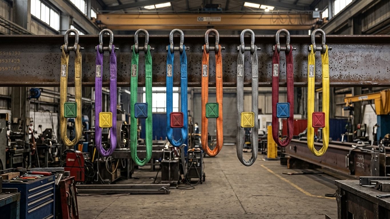
A sling’s marked working load limit (WLL) applies to a straight, vertical pull with undamaged end fittings. Every other way of using it, whether choked, in a basket, at an angle or round a small pin, changes the load it can safely carry.
1. Choosing the sling type
| Type | Strengths | Watch out for | Typical design factor |
|---|---|---|---|
| Wire rope | Robust, cut-resistant, good for heavy and hot work | Kinks, broken wires, crushing, small bend diameters | 5:1 (ASME B30.9 and EN 13414-1) |
| Alloy chain (grade 80/100) | Tough, adjustable, tolerates heat and rough handling | Point loading, stretched or nicked links, heat above the maker’s limit | 4:1 |
| Polyester webbing | Light, protects finished surfaces, flexible | Cuts at edges, heat, chemicals, UV, label damage | 5:1 (ASME) or 7:1 (EN 1492-1) |
| Polyester roundsling | Light, flexible, wraps well, high capacity for weight | Hidden core damage, cuts, heat (inner yarns do the work) | 5:1 (ASME) or 7:1 (EN 1492-2) |
Textile slings lose strength at relatively low temperatures. Follow the maker’s limits, typically around 80–100 °C for polyester, and keep them away from hot work. Alloy chain keeps its rating up to a temperature stated by the maker, then needs a reduction or must be withdrawn after heat exposure.
2. Choke hitch
In a choke hitch the sling bends sharply at the point of choke, and the eye or fitting rubs on the sling body. Capacity falls. EN slings carry a mode factor of 0.8 for choked use. For wire rope, the choker rating is usually about 75–80% of the vertical rating at a normal choke angle of 120° or more. If the choke angle is smaller, the rating drops further:
| Angle of choke | Capacity as % of normal choker rating |
|---|---|
| 120°–180° | 100% |
| 90°–119° | 87% |
| 60°–89° | 74% |
| 30°–59° | 62% |
| 0°–29° | 49% |
A freely hanging load chokes naturally at about 135°. Smaller angles occur when something else supports the load at the same time: turning a load over, tailing a column, or two chokers trying to rotate the load in opposite directions. Never force the choke down towards the load; let it settle.
3. Basket hitch and D/d
In a basket the sling passes under the load (or through a lug) and both legs go to the hook, so in principle it carries twice the vertical WLL. That is only true if the sling is not bent too sharply. The D/d ratio compares the diameter the sling bends round (D) with the sling’s own diameter (d). Bending a wire rope round a small D overstresses its outer wires and reduces its strength.
| D/d ratio | Typical efficiency of a 6-strand wire rope sling bent over a fixed pin |
|---|---|
| 1 | 50% |
| 2 | 65% |
| 4 | 75% |
| 6 | 79% |
| 8 | 83% |
| 10 | 86% |
| 20 | 91% |
| 30 | 93% |
Basket capacity ≈ 2 × vertical WLL × D/d efficiency × cos β, where β is the angle of the legs from vertical. Use the sling maker’s values where they are published.
Example. A 32 mm wire rope sling with a vertical WLL of 10 t is used in a basket round a 160 mm trunnion, with the legs 30° from vertical. D/d = 160 ÷ 32 = 5, efficiency about 77%. Capacity ≈ 2 × 10 × 0.77 × cos 30° = 13.3 t, not the 20 t a quick look suggests.
The same principle applies to shackle pins and hook saddles. A sling eye over a small shackle pin is a bend with a low D/d. Many makers require a minimum pin diameter or a thimble for this reason.
4. Edges and protection
- A sharp edge cuts textile slings in seconds under load and crushes wire rope. A corner counts as sharp if its radius is smaller than the sling’s thickness or diameter.
- Use purpose-made edge protectors, corner pads or sleeves, rated for the sling type. Rags and cardboard are not protection.
- Keep labels and tags readable. A sling with no legible WLL must not be used.
5. Selection checklist
- Calculate the tension in each leg (Chapters 2 and 3).
- Apply the hitch factor (choke, basket) and the D/d efficiency.
- Choose a sling whose reduced capacity is at least the leg tension.
- Check the sling against the environment: edges, temperature and chemicals.
- Confirm it is in date for thorough examination and passes its pre-use check.
6. Worked example: choosing a two-leg choked sling
A 12 t bundle is to be lifted with two slings, each in a choke hitch round the bundle, gathered on the hook. The legs make 40° to the vertical. The choke angle is over 120°, and the manufacturer gives a choke factor of 0.8.
- Load per leg (even split, CoG central): T = 12 ÷ (2 × cos 40°) = 12 ÷ 1.532 = 7.83 t.
- The choke reduces each sling’s capacity to 0.8 × its vertical WLL, so the vertical WLL needed is 7.83 ÷ 0.8 = 9.79 t.
- Select slings with a vertical WLL of at least 10 t, and check that the hook, shackles and any edge protection suit that size.
Had the 12 t been divided by two and the slings chosen at 6 t, each choked leg would have been loaded to 7.83 ÷ (0.8 × 6) = 163% of its choked rating.
The choke angle
The choke factor applies only when the choke angle (the angle the sling makes as it leaves the choke point) is about 120° or more. If the choke is pulled tighter, the capacity falls further. Typical reductions for wire rope used in published handbooks are:
| Choke angle | Percentage of the choke rating |
|---|---|
| 120°–180° | 100% |
| 90°–119° | 87% |
| 60°–89° | 74% |
| 30°–59° | 62% |
| 0°–29° | 49% |
Never force the choke down onto the load with a bar or by hammering the eye. Let it bed in under load. Never choke a sling round its own body against a shackle pin, and put the shackle bow, not the pin, against the sling running through it.
7. Baskets: inward force and crushing
A basket hitch carries the load on both legs, but it also squeezes the load. Each inclined leg pulls inwards with a horizontal force H = T × sin β: a leg carrying 10 t at 30° from vertical pulls inwards with 5 t. For a double basket under a long load, that pull acts across the load at each basket position.
Where the sling wraps round a round object, it presses on it all round the arc of contact. Treating the sling like a rope over a sheave, the average contact pressure for vertical legs is:
p = W ÷ (B × D) W = load carried by that basket, B = width of the sling in contact, D = diameter of the object.
Example. A coated 8 t pipe spool, 508 mm outside diameter, is lifted in two baskets of 100 mm wide webbing, each carrying 4 t (39.2 kN). p = 39.2 ÷ (0.100 × 0.508) = 772 kPa (0.77 MPa). That is enough to mark soft coatings and, on large thin-walled pipe or ducting, to dent or ovalise the wall. Use wider slings, wide flat saddles or cradles, or spread each basket over a timber or plastic sleeve.
8. Inspection and removal from service
Every sling is inspected by the user before each use and thoroughly examined by a competent person at the intervals set by law (in the UK, at least every 6 months for accessories under LOLER). Remove the sling from service if you find any of the following. The detailed limits are in ASME B30.9 and the relevant EN standards; the manufacturer’s limits apply where stricter.
| Sling | Typical removal criteria |
|---|---|
| Wire rope | Broken wires above the standard’s limit (for a single-part sling in ASME B30.9: 10 randomly distributed broken wires in one rope lay, or 5 in one strand in one lay); kinking, crushing, birdcaging or core protrusion; heat damage; severe corrosion or pitting; wear of a third of the outer wire diameter; cracked, deformed or slipping fittings and ferrules; missing identification. |
| Alloy chain | Cracks, nicks or gouges; stretched or bent links (links that no longer hinge freely); wear beyond the maker’s table (EN practice: about 10% loss of link diameter); weld spatter or heat discolouration; damaged or open hooks; missing tag. |
| Webbing and roundslings | Missing or illegible label; cuts, tears, holes or snags; broken or worn stitching in load-bearing seams; melting, charring or weld spatter; chemical burns; stiff or discoloured areas from UV; warning yarns showing or the core exposed on a roundsling; knots. |
Temperature and chemicals
- Wire rope: fibre core about −40 °C to 82 °C (180 °F); steel core (IWRC) up to about 204 °C (400 °F) without reduction, above which the maker’s data is needed.
- Alloy chain: full rating to about 200 °C for most grade 80 and 100 chain; above that use the maker’s reduction table. After exposure to high heat, the chain must be examined before reuse.
- Polyester and nylon (polyamide): −40 °C to about 90–100 °C depending on the standard. Polypropylene: up to 80 °C.
- Chemicals: polyester resists acids but is attacked by strong alkalis; nylon resists alkalis but is attacked by acids. If a sling has been in contact with an unknown chemical, take it out of service and ask the manufacturer.
9. Common mistakes
- Dividing the load by the number of legs and ignoring the leg angle and hitch factor.
- Using the basket rating of a wire rope sling round a small pin or a tight corner, where the D/d ratio cuts the capacity far below the rating.
- Choking round a sharp edge without protection, or relying on a sleeve that the edge will cut straight through.
- Shortening a chain leg by knotting it or wrapping it round the hook, instead of using a proper shortening clutch.
- Leaving a webbing sling in sunlight for months and still trusting its label.
- Mixing slings of different stretch in one lift.
10. Self-check questions
1. A 6 t load is lifted on a two-leg chain sling with legs at 45° from vertical. What is each leg tension?
T = 6 ÷ (2 × cos 45°) = 6 ÷ 1.414 = 4.24 t.
2. A choke hitch with a factor of 0.8 is pulled tight to a choke angle of 75°. What fraction of the sling’s vertical WLL is available?
0.8 × 0.74 = 0.59, so about 59% of the vertical WLL.
3. A 3 t basket carries a steel drum 600 mm in diameter on a 75 mm wide webbing sling. What is the average contact pressure?
W = 3 × 9.81 = 29.4 kN. p = 29.4 ÷ (0.075 × 0.600) = 654 kPa.
4. Which synthetic sling would you choose near an acid process, and which near a caustic wash?
Polyester near acids; nylon (polyamide) near alkalis such as caustic soda. In either case, confirm with the maker and keep the sling clean and dry.
5. A wire rope sling has a fibre core. Can it be used to lift a casting at 150 °C?
No. Fibre-cored rope is limited to about 82 °C. Use a steel-core (IWRC) sling or chain, rated for that temperature, after checking the maker’s data.
General guidance only. It does not replace the manufacturer's data, the applicable standards or the judgement of a competent person.
References
Technical references consulted for this chapter. The text and worked examples are original to LiftPlan Pro.
- J. Keith Anderson, Rigging Engineering Calculations (Industrial Training International).
- Ronald G. Garby, IPT’s Crane and Rigging Training Manual: Mobile, EOT and Tower Cranes (IPT Publishing and Training).
- Rigging Handbook, 2nd edition (Bechtel Equipment Operations, 2002).
- ASME B30.9 Slings; ASME B30.26 Rigging Hardware; ASME B30.10 Hooks.
- BS EN 13414-1 (wire rope slings), BS EN 818-4 (chain slings), BS EN 1492-1/-2 (textile slings).
All 18 chapters
- Load weight and centre of gravity: the two numbers every lift depends on
- Two-leg bridles: unequal legs, offset centre of gravity and lift points at different heights
- Three- and four-leg bridles: how the load really shares between the legs
- Sling selection: sling types, choke and basket hitches, and the D/d ratio
- Rigging hardware: shackles, hooks, eyebolts and wire rope terminations
- Spreader bars and lifting beams: forces, stability and design basis
- Mobile crane capacity: reading the chart, net load, utilisation and reeving
- Outrigger loads and crane mats: from crane reactions to ground pressure
- Tandem lifts, upending and tailing: sharing a load between two cranes
- Wind on cranes and suspended loads: pressure, sail area and limits
- Drifting loads: moving a suspended load between two hoists
- Snatch blocks, winches and anchors: line pull, block loads and anchor design
- Lifting from structure: beams, trolleys, beam clamps and temporary lifting points
- Jacking, skidding and rolling: friction, push forces, support reactions and cribbing
- Side boom pipelayers: pipe weight, load overhang, tipping and lowering-in
- Forklifts: load centre, load moment, attachments and slung loads
- Load securing for road transport: friction, blocking, lashing and tipping to EN 12195-1
- Dynamic loads: hoisting factors, shock loading, snatch lifts and load swing