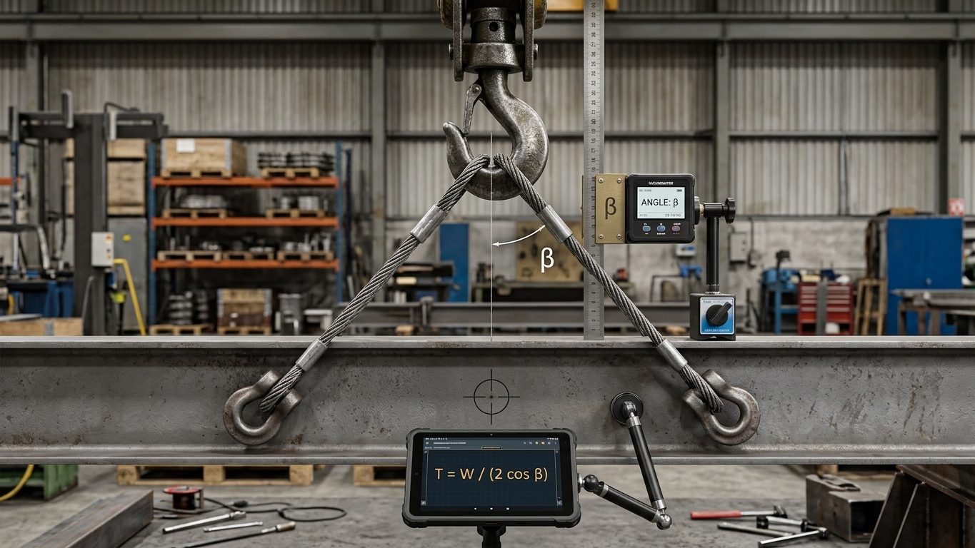
Inside plant rooms, pipe racks, modules and buildings, a crane often cannot reach the final position. Loads are then moved by drifting: the load hangs from two or more hoists (chain blocks, lever hoists or small winches) attached to fixed points, and the rigger shortens one while paying out the other. The load moves sideways, and can be handed from one pair of points to the next, bay by bay.
The method is simple and the equipment is light, which is why it is easy to overload. When two hoists pull at angles, each one can carry more than its share of the weight, and the attachment points are pulled sideways. This chapter shows how to calculate both.
1. Hoist points at the same height
Let the hoists hang from points A and B a span S apart, with the load’s single lifting point (where both hoist hooks meet, usually in one shackle or master link) a horizontal distance a from A and b from B, and a vertical distance y below the line A–B. The CoG hangs directly below that lifting point. Equilibrium of the meeting point gives:
VA = W × b ÷ S VB = W × a ÷ S
H = VA × a ÷ y = W × a × b ÷ (S × y) (the same in both hoists)
TA = √(VA² + H²) TB = √(VB² + H²)
The vertical shares follow the lever rule, exactly as for a two-leg bridle (Chapter 2). The horizontal pull H, which loads both attachment points towards each other, is greatest when the load is midway and grows as the drop y gets smaller.
Worked example: drifting across one bay
An 8 t valve (including its rigging) is drifted from directly under point A to directly under point B. S = 6.0 m; the lifting point stays 2.5 m below the line A–B.
| a (m) | VA (t) | VB (t) | H (t) | TA (t) | TB (t) | Angle A / B from vertical |
|---|---|---|---|---|---|---|
| 0 | 8.00 | 0 | 0 | 8.00 | 0 | 0° / 67.4° |
| 1 | 6.67 | 1.33 | 2.67 | 7.18 | 2.98 | 21.8° / 63.4° |
| 2 | 5.33 | 2.67 | 4.27 | 6.83 | 5.03 | 38.7° / 58.0° |
| 3 | 4.00 | 4.00 | 4.80 | 6.25 | 6.25 | 50.2° / 50.2° |
| 4 | 2.67 | 5.33 | 4.27 | 5.03 | 6.83 | 58.0° / 38.7° |
| 5 | 1.33 | 6.67 | 2.67 | 2.98 | 7.18 | 63.4° / 21.8° |
| 6 | 0 | 8.00 | 0 | 0 | 8.00 | 67.4° / 0° |
Here each hoist must be rated for the full 8 t, because each carries all of it at one end of the move. The horizontal pull on the two attachment points peaks at 4.8 t in the middle. If the attachment points are beam clamps or trolleys, that sideways pull is the critical check (Chapter 13).
2. Why a shallow drift is dangerous
With the load midway, each tension is T = (W ÷ 2) × √(1 + (S ÷ 2y)²). When the hoists are flatter than 60° from vertical (S ÷ 2y greater than 1.73), each hoist carries more than the whole load. For the same 8 t load and 6 m span:
| Drop y (m) | H (t) | Tension in each hoist (t) | Compared with W |
|---|---|---|---|
| 4.0 | 3.00 | 5.00 | 63% |
| 3.0 | 4.00 | 5.66 | 71% |
| 2.0 | 6.00 | 7.21 | 90% |
| 1.5 | 8.00 | 8.94 | 112% |
| 1.0 | 12.00 | 12.65 | 158% |
| 0.75 | 16.00 | 16.49 | 206% |
This is the most common way drifting goes wrong. The load is raised close to the beam to clear an obstacle, the hoists flatten, and two 10 t chain blocks that looked generous for an 8 t valve are each pulling more than 12 t. Set a minimum drop in the lift plan (for example, no hoist flatter than 60° from vertical) and lower the load before drifting it past the middle of the bay.
3. Hoist points at different heights
When A and B are at different heights, the lever rule no longer gives the vertical shares. Use the same equilibrium method as for a two-leg bridle with lift points at different levels. With yA and yB the vertical distances from each hoist point down to the load’s lifting point:
H = W ÷ (yA/a + yB/b) VA = H × yA ÷ a VB = H × yB ÷ b
Example. The 8 t load at a = 2.5 m, b = 3.5 m. Point A is on a lower beam, 2.0 m above the lifting point; point B is 3.0 m above it.
- H = 8 ÷ (2.0/2.5 + 3.0/3.5) = 8 ÷ (0.800 + 0.857) = 4.83 t.
- VA = 4.83 × 0.800 = 3.86 t; VB = 4.83 × 0.857 = 4.14 t.
- TA = √(3.86² + 4.83²) = 6.18 t; TB = √(4.14² + 4.83²) = 6.36 t.
With level hoist points the lever rule would have given VA = 4.67 t. The lower point A takes less of the vertical load than the plan position suggests, because its hoist is flatter. If you used the lever rule, you would have the wrong hoist marked as the heavier one.
4. Handing a load from one pair of points to the next
To move a load several bays, it is passed along a line of points. A typical sequence for a load going from point 1 towards point 4:
- Load hangs from hoists on points 1 and 2. Drift it until it is under point 2, so hoist 2 carries nearly all of it.
- Attach a third hoist from point 3 to the load’s lifting point. Take up the slack with it until it just starts to carry load.
- Pay out hoist 1 until it is slack, then remove it. The load now hangs from points 2 and 3.
- Drift towards point 3 by shortening hoist 3 and paying out hoist 2. Repeat for the next bay.
Each step changes only one hoist at a time. Never have three hoists all tight at once on a single lifting point unless their sharing has been calculated: three hoists to one point, like a three-leg bridle, can be solved, but a rigger cannot see which one is carrying what. Agree the signals before starting: the person in charge calls each hoist by number.
5. The equipment and attachment points
- Hoists. Chain blocks and lever hoists are rated for an in-line pull. Each must be rated for the largest tension it will carry anywhere in the move, which may be the full load. Never extend a hand chain or lever to gain force; if it will not move with one person’s normal effort, something is overloaded or jammed.
- Top attachments. The attachment point sees the full inclined tension, so it must be rated for that load at that angle. A beam clamp, trolley or padeye rated only for a vertical load must not be used for drifting unless the maker allows an angled pull (Chapter 13).
- Load attachment. Bring all hoist hooks into one shackle bow or master link, never hook one hoist onto another hoist’s chain. A shackle with two hooks at an angle in its bow must be rated for the angle (Chapter 5).
- Chain angle at the hoist body. The hoist body hangs in line with its load chain, but the hand chain must hang freely. A hand chain dragging over an edge or the load is a sign the geometry is wrong.
5a. When one of the supports is a crane
A common variation is to hand a load from a crane to a chain block on a beam, or the other way round. The difference is that a crane hook must stay plumb: a crane is not designed to be pulled sideways by its hoist rope (Chapter 7). In a drift between two chain blocks, both hoists lean and the horizontal pull H balances between them. If one of the “hoists” is a crane, the horizontal pull from the chain block would drag the crane rope out of plumb.
Example. In the 8 t drift above, with the load midway, H = 4.8 t. If point B were a crane hook, its rope would have to lean about 50° from vertical to provide that force, which is impossible without huge side load on the boom. In practice the rule is:
- Keep the crane rope vertical at all times. Move the crane hook (by slewing, luffing or trolleying) to follow the load, and use the chain block only to take or release vertical load.
- Transfer the load in steps: crane takes the load, chain block is attached vertically above the landing position, crane lowers while the chain block takes up, then the crane is released.
- If the chain block cannot hang vertically above the load, the transfer is a drift and the crane must not be part of it. Use two hoists on fixed points.
Write the transfer as a numbered sequence in the plan, with who operates what and the expected load on each support at each step.
6. Common mistakes
- Choosing hoists for half the load, when each carries the full load at the end of the move.
- Drifting with the load close up to the beam, so the hoists are nearly horizontal.
- Attaching to beam clamps or trolleys that are only rated for vertical loads.
- Hooking a chain block onto pipework, cable tray or handrails to gain a better angle.
- Letting two people operate hoists at the same time without one person in charge.
- Ignoring the swing when the load moves from one hoist to another: it moves sideways towards the new hoist as it takes the load.
7. Field checklist
- Every attachment point identified, rated and marked for the inclined load it will carry.
- Hoist tensions calculated at the start, midway, the end of each bay and at the minimum planned drop.
- Minimum drop (or maximum hoist angle) written into the plan and marked on site if practical.
- Route clear of people and obstructions; exclusion zone under the load and the hoists.
- One person in charge calling each hoist by number; hand-over steps written as a sequence.
- Hoists inspected before use; chain not twisted; load chain end stops fitted.
8. Self-check questions
1. A 5 t load is 1.5 m from point A on a 4.5 m span, 2.0 m below level hoist points. What is the horizontal pull?
b = 3.0 m. H = 5 × 1.5 × 3.0 ÷ (4.5 × 2.0) = 2.5 t.
2. What are the hoist tensions in question 1?
VA = 5 × 3.0 ÷ 4.5 = 3.33 t; VB = 1.67 t. TA = √(3.33² + 2.5²) = 4.17 t; TB = √(1.67² + 2.5²) = 3.01 t.
3. A 3 t load is midway across a 5 m span. What is the smallest drop at which neither hoist carries more than 3 t?
Each tension equals W when S ÷ 2y = √3, so y = 5 ÷ (2 × 1.732) = 1.44 m. Any shallower and each hoist carries more than the load.
4. Why must each hoist usually be rated for the whole load?
At the start and end of each bay the load hangs directly under one hoist, which then carries all of it.
5. Why change only one hoist at a time when handing a load to the next point?
So that the load is always carried by a known, calculable pair of hoists, and so the load’s sideways movement is small and controlled.
General guidance only. It does not replace the manufacturer's data, the applicable standards or the judgement of a competent person.
References
Technical references consulted for this chapter. The text and worked examples are original to LiftPlan Pro.
- J. Keith Anderson, Rigging Engineering Calculations (Industrial Training International).
- ASME B30.9 Slings; ASME B30.26 Rigging Hardware; ASME B30.10 Hooks.
- ASME B30.16 Overhead Underhung and Stationary Hoists; ASME B30.21 Lever Hoists; BS EN 13157 Hand-powered lifting equipment.
All 18 chapters
- Load weight and centre of gravity: the two numbers every lift depends on
- Two-leg bridles: unequal legs, offset centre of gravity and lift points at different heights
- Three- and four-leg bridles: how the load really shares between the legs
- Sling selection: sling types, choke and basket hitches, and the D/d ratio
- Rigging hardware: shackles, hooks, eyebolts and wire rope terminations
- Spreader bars and lifting beams: forces, stability and design basis
- Mobile crane capacity: reading the chart, net load, utilisation and reeving
- Outrigger loads and crane mats: from crane reactions to ground pressure
- Tandem lifts, upending and tailing: sharing a load between two cranes
- Wind on cranes and suspended loads: pressure, sail area and limits
- Drifting loads: moving a suspended load between two hoists
- Snatch blocks, winches and anchors: line pull, block loads and anchor design
- Lifting from structure: beams, trolleys, beam clamps and temporary lifting points
- Jacking, skidding and rolling: friction, push forces, support reactions and cribbing
- Side boom pipelayers: pipe weight, load overhang, tipping and lowering-in
- Forklifts: load centre, load moment, attachments and slung loads
- Load securing for road transport: friction, blocking, lashing and tipping to EN 12195-1
- Dynamic loads: hoisting factors, shock loading, snatch lifts and load swing