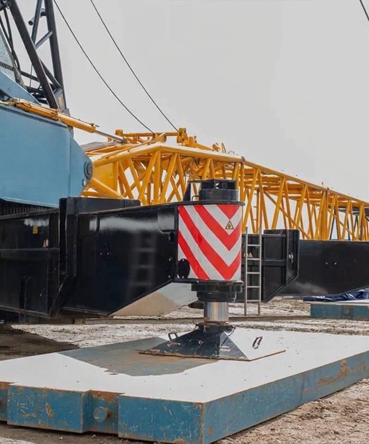
Many crane overturns start with the ground, not the crane. The load chart assumes firm, level support. It is the lift planner’s job to show that the ground, or the structure under the crane, can carry the outrigger or crawler loads with the mats provided.
1. Outrigger reactions
The crane’s own weight and the load moment are shared between the outriggers according to where the boom points. The highest single reaction normally occurs when the boom is over or near one outrigger. Use the manufacturer’s outrigger load calculator or data for the actual configuration, radius and slew range. The statics below show why the loads can be so large.
Illustration (two-dimensional, boom straight over the front). Front and rear outrigger lines are 7.0 m apart, with the centre of rotation midway. The crane weighs 40 t and its CoG is 0.5 m behind the centre of rotation, towards the counterweight. The total hook load is 10 t at 12 m radius. Taking moments about the rear outrigger line:
Rfront × 7.0 = 40 × (3.5 − 0.5) + 10 × (3.5 + 12.0) = 120 + 155 = 275 ⇒ Rfront = 39.3 t (19.6 t per front outrigger); Rrear = 50 − 39.3 = 10.7 t
When the boom swings over a corner, one outrigger can take a large share of that 39 t. This is why mats must be sized for the worst slew position, not the average.
For crawler cranes, the track pressure is not uniform. The load moment shifts the reaction towards the front of the tracks, giving a trapezoidal or triangular pressure distribution. Take the maximum pressure from the manufacturer’s data.
2. Required mat area
Required area A = outrigger load P ÷ allowable ground bearing pressure qallow
The allowable bearing pressure must come from a site assessment or geotechnical data for that location, allowing for voids, services, recent excavation, rain and slopes. A competent engineer must assess crane support on a structure (slab, deck, pipe rack or culvert).
Example. Outrigger load 60 t (589 kN) on a 0.6 m × 0.6 m float; allowable bearing pressure 150 kPa. Required area = 589 ÷ 150 = 3.92 m². Try a 2.0 m × 2.0 m timber mat (4.0 m²): applied pressure q = 589 ÷ 4.0 = 147 kPa ≤ 150 kPa. Acceptable for bearing.
3. Check that the mat can spread the load
A mat only spreads the load over its full area if it is stiff and strong enough. Treat each side of the mat beyond the float as a cantilever of length a, loaded by the ground pressure q from below. Per metre width, for a solid mat of thickness d:
Bending stress f = 3 q a² ÷ d² Shear stress v = 1.5 q a ÷ d
In the example, a = (2.0 − 0.6) ÷ 2 = 0.7 m and d = 0.3 m:
- f = 3 × 147 × 0.7² ÷ 0.3² = 2,403 kPa = 2.4 MPa
- v = 1.5 × 147 × 0.7 ÷ 0.3 = 515 kPa = 0.52 MPa
Compare these with the allowable stresses for the actual timber grade, from the mat supplier. As a guide, the reference handbook uses about 10 MPa (1,500 psi) in bending and 0.86 MPa (125 psi) in shear for construction-grade timber. Both checks pass here with a good margin. If they did not, use a thicker or stiffer mat, a steel plate under the float, or a two-layer mat system with the layers crossed.
4. Practical rules
- Place the float at the centre of the mat, with the mat on firm, level, compacted ground. Never bridge a void or a soft spot.
- Do not stack loose timbers in a pyramid under a float. Use purpose-made, rated mats or engineered steel plates.
- Keep mats clear of trenches and excavation edges. A common rule is to stay back at least the depth of the excavation, unless an engineer assesses it.
- Recheck after heavy rain and during long lifts. Watch for settlement and keep the crane level within the chart’s tolerance.
5. Outrigger reactions as the crane slews
The maker’s outrigger load calculator or published reactions should always be used where available. To understand how the loads move, a simple rigid-body model works well. With total vertical load V (crane, counterweight, load and rigging) and overturning moment M about the slew centre, four outriggers at a spread of a (along the carrier) by b (across it), and the boom at slew angle θ from the carrier axis:
R = V ÷ 4 ± (M cos θ) ÷ (2a) ± (M sin θ) ÷ (2b)
(The signs are + for the outriggers on the boom side of each axis.) This assumes a rigid carrier and equal outrigger stiffness, and ignores the offset of the crane’s own CoG from the slew centre.
Example. V = 50 t, M = 100 t·m, a = 7.0 m, b = 6.6 m.
| Slew angle θ | Largest reaction | Smallest reaction |
|---|---|---|
| 0° (over the end) | 19.64 t | 5.36 t |
| 30° | 22.47 t | 2.53 t |
| 45° (over a corner) | 22.91 t | 2.09 t |
| 60° | 22.63 t | 2.37 t |
| 90° (over the side) | 20.08 t | 4.92 t |
The largest outrigger load does not occur with the boom over the end or the side, but close to a corner, where the moment is shared by both axes. Size every outrigger mat for the largest reaction anywhere in the planned slew arc, not just at the pick and set positions. A falling reaction is also a warning: if one outrigger approaches zero, the crane is near its tipping limit in that direction.
6. Crawler cranes: track pressure
A crawler crane spreads its load along two tracks. With the boom along the tracks, the pressure varies along each track. If V is the total vertical load, L the track contact length, w the width of each track and e = M ÷ V the eccentricity along the tracks:
- If e ≤ L/6: trapezoidal pressure, p = V ÷ (2wL) × (1 ± 6e ÷ L).
- If e > L/6: part of the track lifts off. Contact length = 3 × (L/2 − e), and pmax = 2V ÷ (2w × contact length).
Example. V = 150 t, tracks 7.0 m × 1.0 m each.
- M = 150 t·m: e = 1.0 m, within L/6 = 1.17 m. p = 150 ÷ 14 × (1 ± 0.857) = 19.9 t/m² (195 kPa) at the front and 1.53 t/m² (15 kPa) at the rear.
- M = 300 t·m: e = 2.0 m, beyond L/6. Contact length = 3 × (3.5 − 2.0) = 4.5 m; pmax = 300 ÷ (2 × 4.5) = 33.3 t/m² (327 kPa).
Doubling the moment raised the peak pressure by two thirds and took a third of the track out of contact. Crane makers publish track pressure diagrams for each configuration; use them, and use this method to understand and check them. With the boom over the side, one track carries most of the load and the calculation is done across the tracks.
7. Mat capacity: the effective length method
A mat only spreads the load as far as it is stiff and strong enough. A widely used approach (described by Duerr for timber and steel mats) is to treat the mat either side of the float as a cantilever loaded by the ground pressure, and to find the cantilever length c at which the mat reaches its bending or shear limit when the ground is at its allowable pressure q:
Bending: f = 3qc² ÷ d² → c = d × √(fallow ÷ 3q)
Shear: v = 1.5qc ÷ d → c = vallow × d ÷ (1.5q)
Use the smaller c. Effective length Leff = float width + 2c (not more than the mat length). Capacity = Leff × mat width × q.
Example. Hardwood mat 1.2 m wide × 0.3 m deep; float 0.6 m square; allowable ground pressure q = 150 kPa. Typical timber allowables of about 10.3 MPa in bending and 0.86 MPa in shear (use the values for the actual grade and condition):
- Bending: c = 0.3 × √(10,300 ÷ 450) = 0.3 × 4.78 = 1.43 m.
- Shear: c = 860 × 0.3 ÷ 225 = 1.15 m (governs).
- Leff = 0.6 + 2 × 1.15 = 2.90 m. Capacity = 2.90 × 1.2 × 150 = 522 kN = 53 t.
The largest outrigger reaction from Section 5 is 22.9 t, so this mat is adequate, with an average pressure under the effective area of about 65 kPa. A longer mat would add nothing, because the extra length beyond 1.15 m from the float would not carry load. To increase capacity, use a deeper mat, a stiffer material (steel or composite), or a two-layer arrangement with the layers crossed.
8. Ground: what lies beneath the mat
The mat calculation is only as good as the allowable ground pressure. The following presumed values are often quoted for preliminary assessment of undisturbed natural ground. They are indicative only; a ground investigation or a geotechnical engineer should confirm the value for any heavy lift.
| Ground | Presumed allowable bearing (kPa) |
|---|---|
| Dense gravel or sand and gravel | over 600 |
| Medium dense gravel or sand and gravel | 200–600 |
| Compact sand | over 300 |
| Medium dense sand | 100–300 |
| Stiff clay | 150–300 |
| Firm clay | 75–150 |
| Soft clay or silt | under 75 |
| Made ground or fill | assess case by case |
- Hazards below: drains, culverts, basements, voids, buried tanks and services. A crane outrigger above a 1 m sewer can punch through a surface that looks solid.
- Excavations and slopes: keep outriggers well back from the edge. A common rule of thumb is a distance at least equal to the depth of the excavation for firm ground, and more for poor ground or where water is present; confirm with a geotechnical assessment.
- Water: rain can halve the bearing capacity of some soils overnight. Re-check the ground after heavy rain and before resuming a long lift.
- Platforms: crane platforms of crushed stone over weak ground must be designed as such (for example to BRE 470 for tracked plant). The platform certificate should state the loads and areas it is designed for.
9. Common mistakes
- Checking the outrigger at the pick and set positions only, and missing the corner during the slew.
- Using a long mat and assuming the whole length carries load.
- Stacking mats without crossing the layers, or using mats that are rotten, split or warped.
- Placing a mat on uneven ground so that it bears on a hump or a stone and bends over it.
- Ignoring ground conditions because the crane has stood there before, with a lighter load or a different configuration.
10. Self-check questions
1. With V = 60 t, M = 120 t·m and a = b = 7.0 m, what is the largest outrigger load with the boom over the end?
R = 60 ÷ 4 + 120 ÷ (2 × 7.0) = 15 + 8.57 = 23.6 t.
2. An outrigger load of 30 t (294 kN) on ground allowing 200 kPa: what mat area is needed?
294 ÷ 200 = 1.47 m² effective, for example a mat 1.2 m wide with an effective length of at least 1.23 m. Check the mat’s effective length as in Section 7.
3. A crawler’s eccentricity is 0.9 m on a 6 m track. Is the pressure a trapezoid or a triangle?
L/6 = 1.0 m; e = 0.9 m is within it, so it is a trapezoid, and the whole track stays in contact.
4. A 0.3 m deep timber mat has shear allowable 0.86 MPa and the ground allowable is 100 kPa. What is the shear-limited cantilever length?
c = 860 × 0.3 ÷ (1.5 × 100) = 1.72 m.
5. Why can the outrigger nearest the boom on a 45° slew carry more than when the boom is over the end?
Over a corner the moment is resisted by both outrigger axes at once, and both components add on the same corner outrigger.
General guidance only. It does not replace the manufacturer's data, the applicable standards or the judgement of a competent person.
References
Technical references consulted for this chapter. The text and worked examples are original to LiftPlan Pro.
- Rigging Handbook, 2nd edition (Bechtel Equipment Operations, 2002).
- J. Keith Anderson, Rigging Engineering Calculations (Industrial Training International).
- ASME B30.5 Mobile and Locomotive Cranes; BS EN 13000 Mobile cranes; BS 7121 Code of practice for safe use of cranes.
All 18 chapters
- Load weight and centre of gravity: the two numbers every lift depends on
- Two-leg bridles: unequal legs, offset centre of gravity and lift points at different heights
- Three- and four-leg bridles: how the load really shares between the legs
- Sling selection: sling types, choke and basket hitches, and the D/d ratio
- Rigging hardware: shackles, hooks, eyebolts and wire rope terminations
- Spreader bars and lifting beams: forces, stability and design basis
- Mobile crane capacity: reading the chart, net load, utilisation and reeving
- Outrigger loads and crane mats: from crane reactions to ground pressure
- Tandem lifts, upending and tailing: sharing a load between two cranes
- Wind on cranes and suspended loads: pressure, sail area and limits
- Drifting loads: moving a suspended load between two hoists
- Snatch blocks, winches and anchors: line pull, block loads and anchor design
- Lifting from structure: beams, trolleys, beam clamps and temporary lifting points
- Jacking, skidding and rolling: friction, push forces, support reactions and cribbing
- Side boom pipelayers: pipe weight, load overhang, tipping and lowering-in
- Forklifts: load centre, load moment, attachments and slung loads
- Load securing for road transport: friction, blocking, lashing and tipping to EN 12195-1
- Dynamic loads: hoisting factors, shock loading, snatch lifts and load swing