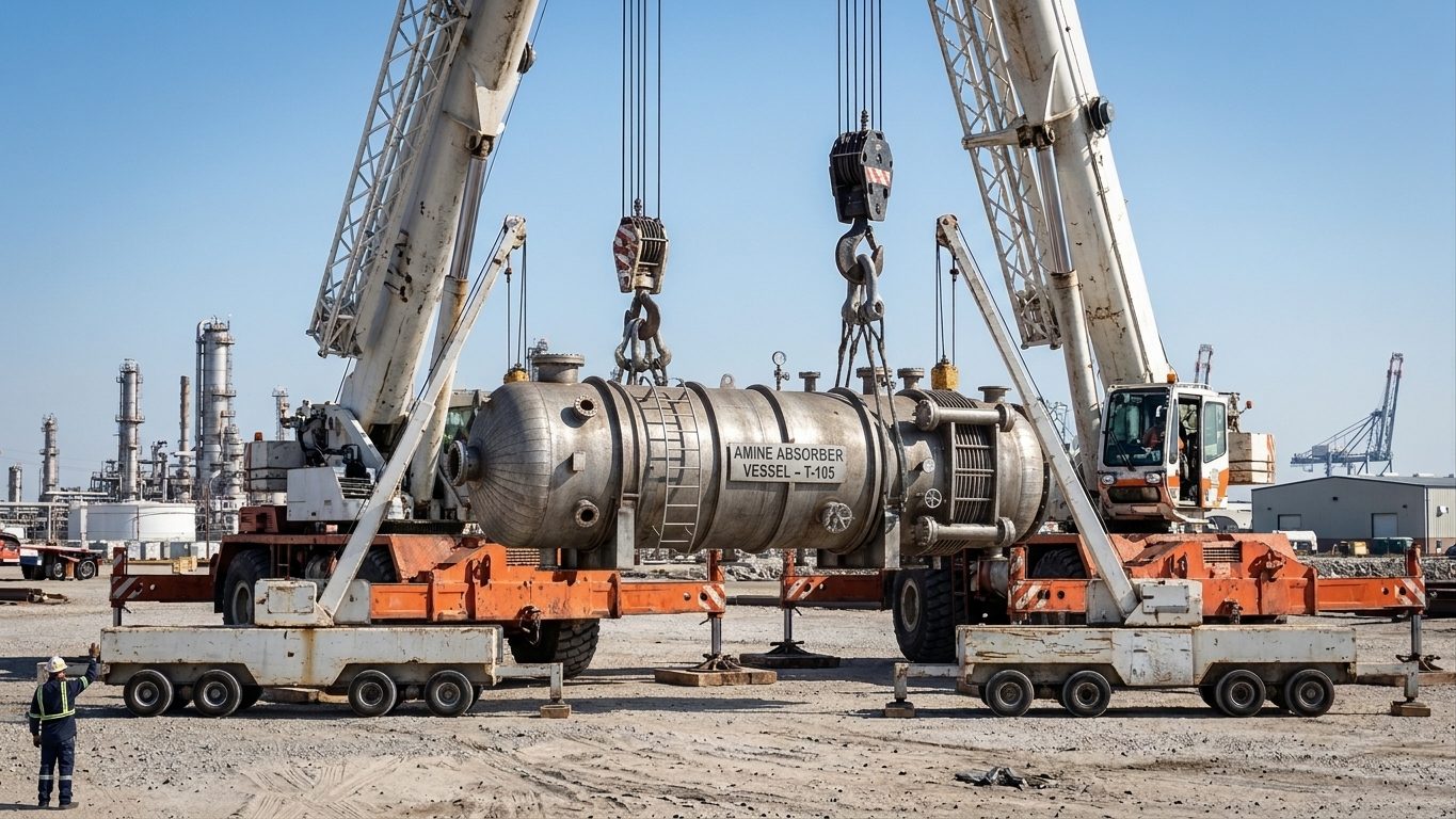
A common and dangerous assumption is that a four-leg bridle shares the load four ways. On a rigid load it almost never does. Small differences in sling length, sling stretch or lug height decide which legs carry the weight.
Three legs: statically determinate
Three lift points, not in a straight line, with the hook above the CoG and the CoG inside the triangle they form, can be solved exactly. With the lift points at the same height, the vertical components follow from moments about the CoG in both directions:
V₁ + V₂ + V₃ = W Σ Vᵢ (xᵢ − x̄) = 0 Σ Vᵢ (yᵢ − ȳ) = 0
Example. A 30 t load with lift points at P₁ (0, 0), P₂ (4.0, 0) and P₃ (2.0, 3.0) m. The CoG is at (1.6, 1.0) m and the hook is 4.0 m above the lift points.
- Moments about the x-axis (only P₃ is off it): V₃ = 30 × 1.0 ÷ 3.0 = 10.0 t
- Moments about the y-axis: 4.0 V₂ + 2.0 × 10 = 30 × 1.6, so V₂ = 7.0 t
- V₁ = 30 − 10 − 7 = 13.0 t
Leg tensions are T = V × L ÷ h, with L the length from hook to each lift point:
| Leg | Vertical load (t) | Leg length (m) | Angle from vertical | Tension (t) |
|---|---|---|---|---|
| 1 | 13.0 | 4.42 | 25.3° | 14.37 |
| 2 | 7.0 | 4.77 | 33.0° | 8.35 |
| 3 | 10.0 | 4.49 | 27.0° | 11.22 |
Note that the most heavily loaded leg (1) is the one nearest the CoG, not the one at the flattest angle.
Four legs: statically indeterminate
With four legs to one hook there are more unknowns than equilibrium equations. On a stiff load, such as a skid, module, vessel or precast unit, two diagonally opposite legs can end up carrying almost all the weight. The other two only steady the load. A few millimetres of difference in sling length is enough.
Size four-leg rigging in one of these ways:
- Two-leg assumption. Size each leg (sling, shackle and lug) as if only two diagonal legs carry the full load. Then check the CoG offset with the Chapter 2 method on each diagonal.
- Make the load share. Use rigging that equalises: a spreader frame, an equalising sheave or beam on one pair of legs, or chain hoists with load cells to set each leg’s share.
- Flexible loads. Only a genuinely flexible load (for example a bundle that can bend to suit the legs) shares reliably between all four legs. Do not assume it for steel structures.
Example. A 40 t module on a four-leg bridle with all legs at 45° from vertical:
- Shared four ways: 40 ÷ 4 ÷ cos 45° = 14.1 t per leg. Unsafe assumption.
- Carried by two legs: 40 ÷ 2 ÷ cos 45° = 28.3 t per leg. Size the legs for this.
Marked ratings of multi-leg slings
Three- and four-leg slings to EN 13414-1 and EN 818-4 are marked using the uniform load method (mode factor 2.1 × single-leg WLL for 0–45°, 1.5 × for 45–60°). The mode factor already allows for uneven sharing on symmetrical loads within the marked angle. It does not cover an offset CoG, unequal leg lengths or lugs at different heights. In those cases, calculate each leg’s tension and compare it with the single-leg WLL.
The vector method for three legs
Lever arithmetic in plan works only when all lift points are at the same level. When they are not, use the fact that every leg points at the hook. Put the origin anywhere convenient, with the hook at (xh, yh, zh) directly above the CoG. For each lift point i at (xᵢ, yᵢ, zᵢ), the leg runs along the vector dᵢ = (xh − xᵢ, yh − yᵢ, zh − zᵢ), and its tension is Tᵢ = kᵢ × |dᵢ| for some unknown kᵢ. Equilibrium of the hook gives three equations:
Σ kᵢ (xh − xᵢ) = 0 Σ kᵢ (yh − yᵢ) = 0 Σ kᵢ (zh − zᵢ) = W
then Vᵢ = kᵢ (zh − zᵢ) and Tᵢ = kᵢ × leg length.
Three equations, three unknowns: a three-leg bridle is always statically determinate, as long as the CoG lies inside the triangle formed by the lift points in plan. If the CoG is outside that triangle, one k comes out negative, which means that leg would have to push. It cannot, so the load will tip.
Worked example
A 30 t load with lift points 1 at (0, 0), 2 at (4.0, 0) and 3 at (1.5, 3.0) in metres. CoG in plan at (1.6, 1.2). Hook 4.0 m above lift points 1 and 2.
| Lift point | All three at the same level | Lift point 3 raised 0.8 m | ||||
|---|---|---|---|---|---|---|
| Leg length (m) | V (t) | T (t) | Leg length (m) | V (t) | T (t) | |
| 1 | 4.472 | 10.50 | 11.74 | 4.472 | 11.41 | 12.76 |
| 2 | 4.817 | 7.50 | 9.03 | 4.817 | 8.15 | 9.82 |
| 3 | 4.387 | 12.00 | 13.16 | 3.673 | 10.43 | 11.98 |
With the lift points level, the vertical shares are exactly what the plan lever rule gives. Raising lift point 3 by 0.8 m moves about 1.6 t of vertical load from leg 3 onto legs 1 and 2, and the largest tension moves from leg 3 to leg 1. The total is still 30 t. The raised lift point has a shorter, steeper leg, but the horizontal balance at the hook forces the other two legs to pull harder. On a load with lift points on different decks or courses, do not assume the plan shares.
Checking a four-leg bridle by diagonal pairs
With four legs, small differences in sling length, stretch and lift point height decide which legs actually carry the load (see above). A practical and conservative check, used widely in heavy rigging, is to assume the load is carried by one diagonal pair and to analyse each diagonal as a two-leg bridle:
- Draw the two diagonals in plan.
- Project the CoG onto each diagonal (it will usually be close to both). Take the distances along the diagonal from the CoG to each end.
- Use the lever rule along that diagonal for the vertical shares, then T = V × leg length ÷ hook height, with the true leg length from the hook above the CoG.
- Size every leg for the largest tension found in either diagonal.
Worked example
A 40 t module, lift points at the corners of a 6.0 m × 4.0 m rectangle, CoG at (2.5, 1.8) from corner 0, hook 4.0 m above the lift points.
- Diagonal 0–2 (7.21 m long): the CoG projects 3.08 m from corner 0 and 4.13 m from corner 2. V₀ = 40 × 4.13 ÷ 7.21 = 22.9 t; V₂ = 17.1 t. Leg 0 is 5.05 m long, so T₀ = 22.9 × 5.05 ÷ 4.0 = 28.9 t; T₂ = 24.6 t.
- Diagonal 1–3: V₁ = 18.3 t, V₃ = 21.7 t; T₁ = 25.7 t, T₃ = 28.2 t.
- If the load shared evenly between four legs, the largest tension would be only about 14.4 t.
The diagonal check gives about twice the even-sharing figure. That is the real margin you need if one diagonal pair goes slack, which can happen with a stiff load, a few centimetres of length difference or a lift point that sits slightly lower. If the CoG is well off both diagonals, the diagonal check cannot balance moments about the diagonal; the two legs on the CoG side will carry it, and you should treat the lift as a three-leg lift with the worst leg removed, or make it determinate.
Making four legs share predictably
If the diagonal-pair tensions are too high for the slings or lift points you have, make the rigging determinate instead of buying bigger slings:
- Spreader with two bridles. Hang a two-leg bridle from each end of a spreader beam. Each pair now shares by the lever rule, and the spreader shares between the pairs (Figure 3.3, left).
- Equalising sheaves or rolling blocks. One sling reeved through a sheave on each side forces equal tension in the two legs it serves. The load will move or tilt until the geometry suits equal tensions, so this works best when the CoG is near the centre (Chapter 6).
- Adjustable legs with load cells. Chain blocks or hydraulic cylinders in two legs, adjusted at the trial lift until the load cells read the calculated values.
- Flexible or light loads. A flexible frame will twist and spread the load among all four legs. Do not count on that for a stiff module or a vessel.
Common mistakes
- Assuming each leg of a four-leg sling carries a quarter of the load.
- Using the plan lever rule for lift points at different heights.
- Lifting with the CoG outside the triangle of a three-leg lift, or close to one side of it, where a small movement tips the load.
- Mixing sling types in one bridle (chain with wire rope, or wire rope with polyester): they stretch differently, so the stiffer legs take more.
- Leaving a spare leg of a four-leg chain sling hanging free, where it can swing and snag. Hook unused legs back to the master link.
Field checklist
- CoG inside the lift point triangle (three legs) or close to both diagonals (four legs).
- Lift point heights known; vector method used if they differ.
- Four-leg lifts checked by diagonal pairs, or the rigging made determinate.
- All legs of the same type, material and length tolerance.
- Leg angles within the limits of the marked rating (normally 0–45° from vertical, with a reduced rating up to 60°).
- Trial lift watched for slack legs; stop and adjust if one leg is visibly loose.
Self-check questions
1. Why is a three-leg bridle statically determinate and a four-leg bridle not?
At the hook there are three equilibrium equations (two horizontal, one vertical). Three legs give three unknown tensions, so they can be solved. Four legs give four unknowns, so the sharing depends on the stiffness and exact lengths of the legs.
2. Lift points at (0, 0), (5, 0) and (2.5, 4) carry a 24 t load with its CoG at (2.5, 1.5), all at the same level. What does each carry?
By symmetry about x = 2.5, V₁ = V₂. Moments about the line y = 0: V₃ × 4 = 24 × 1.5, so V₃ = 9 t; V₁ = V₂ = (24 − 9) ÷ 2 = 7.5 t.
3. A four-leg sling rated 30 t at 0–45° is used on a 25 t load. Is that always acceptable?
Not necessarily. Many marked ratings for three- and four-leg slings assume only three legs share (EN practice uses a factor of 2.1 × single-leg WLL, not 4). If the CoG is off-centre or the load is stiff, two legs may carry most of the load. Check the diagonal pair tensions against the single-leg WLL.
4. In the 40 t module example, which leg governs, and what single-leg WLL is needed?
Leg 0 on diagonal 0–2, at 28.9 t. Each leg needs a single-leg vertical WLL of at least 28.9 t at that angle, so in practice a 30 t or larger leg.
5. What does a negative k (or negative V) mean in the vector method?
That leg would have to push rather than pull. The CoG lies outside the area the lift points can support, so the load would tip. Change the lift points or the rigging.
General guidance only. It does not replace the manufacturer's data, the applicable standards or the judgement of a competent person.
References
Technical references consulted for this chapter. The text and worked examples are original to LiftPlan Pro.
- J. Keith Anderson, Rigging Engineering Calculations (Industrial Training International).
- Rigging Handbook, 2nd edition (Bechtel Equipment Operations, 2002).
- BS EN 13414-1 (wire rope slings), BS EN 818-4 (chain slings), BS EN 1492-1/-2 (textile slings).
All 18 chapters
- Load weight and centre of gravity: the two numbers every lift depends on
- Two-leg bridles: unequal legs, offset centre of gravity and lift points at different heights
- Three- and four-leg bridles: how the load really shares between the legs
- Sling selection: sling types, choke and basket hitches, and the D/d ratio
- Rigging hardware: shackles, hooks, eyebolts and wire rope terminations
- Spreader bars and lifting beams: forces, stability and design basis
- Mobile crane capacity: reading the chart, net load, utilisation and reeving
- Outrigger loads and crane mats: from crane reactions to ground pressure
- Tandem lifts, upending and tailing: sharing a load between two cranes
- Wind on cranes and suspended loads: pressure, sail area and limits
- Drifting loads: moving a suspended load between two hoists
- Snatch blocks, winches and anchors: line pull, block loads and anchor design
- Lifting from structure: beams, trolleys, beam clamps and temporary lifting points
- Jacking, skidding and rolling: friction, push forces, support reactions and cribbing
- Side boom pipelayers: pipe weight, load overhang, tipping and lowering-in
- Forklifts: load centre, load moment, attachments and slung loads
- Load securing for road transport: friction, blocking, lashing and tipping to EN 12195-1
- Dynamic loads: hoisting factors, shock loading, snatch lifts and load swing