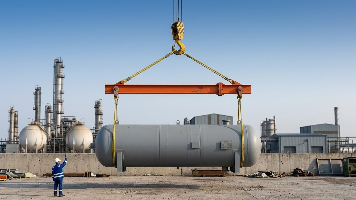
Below-the-hook devices let you lift long or delicate loads with near-vertical slings, reduce headroom, and keep the sling forces off the load’s sides. There are two basic types, and they behave very differently.
Spreader bar: a strut in compression
A spreader has two top slings from the hook to its ends and two (or more) vertical drop slings to the load. The inward pull of the inclined top slings puts the bar in compression. Symmetrical case, with top slings at β from vertical:
Top sling tension T = (W ÷ 2) ÷ cos β Compression in the bar C = (W ÷ 2) × tan β
Example. W = 40 t (load plus drop rigging and spreader weight), top slings at 45°: T = 20 ÷ 0.707 = 28.3 t per top sling; C = 20 × 1.0 = 20 t compression. At 60°, T rises to 40 t and C to 34.6 t. Flatter top slings make the spreader work much harder.
Because it carries mainly axial compression, a spreader is light for its capacity, but it must be checked for buckling. Its rated capacity is only valid for the sling angle it was designed for. Using shorter top slings than specified can overload it.
Lifting beam: a member in bending
A lifting beam hangs from one or two points at the top and carries the load from lugs underneath. It works in bending. For a beam lifted at its centre, carrying W ÷ 2 at each end a distance L apart:
Maximum bending moment M = W × L ÷ 4
Example. W = 40 t (392 kN), L = 6.0 m: M = 392 × 6.0 ÷ 4 = 588 kN·m. That needs a substantial section, much heavier than a 6 m spreader for the same load. Lifting beams are chosen where headroom is limited or there is no room for top slings.
Stability: keep the lift points above the CoG
With vertical drop slings, the load is stable only if the lift points are above its centre of gravity. If they are below it, as with a tall, narrow item lifted from base lugs with vertical slings, the load can roll over in the rigging the moment it is disturbed. Remedies:
- Use lift points above the CoG (top lugs or trunnions).
- Angle the drop slings inward so their lines cross above the CoG.
- Use a cradle or frame that captures the load.
Off-centre CoG
If the CoG is not central, the hook must still end up above it. Position the top lug (on a single-point beam) or adjust the top sling lengths (on a spreader) so that the hook is over the combined CoG of load plus spreader. Then calculate each drop sling with the lever rule from Chapter 2. Adjustable spreaders with several lug positions make this easier.
Design, marking and testing
- Design below-the-hook devices to ASME BTH-1 (or an equivalent national standard), with the appropriate design category and service class for how often and how hard the device is used. Take the device’s own weight into account.
- ASME B30.20 requires a proof load test before first use (normally 125% of rated load), a legible rated load and weight marking, and documented inspections.
- Under LOLER, a spreader or beam is a lifting accessory. It needs a declaration of conformity or test certificate and a thorough examination at least every 6 months, or as the examination scheme requires.
- Never modify, weld to or drill a lifting beam without the designer’s approval and a re-test.
Worked example: off-centre CoG on a spreader
A 40 t load (including the lower slings) hangs from a spreader with a 6.0 m span between the lower lift points. The CoG is 2.5 m from end A. The hook is 3.0 m above the spreader’s top lift points and directly above the CoG.
- Lower slings, vertical: VA = 40 × 3.5 ÷ 6.0 = 23.33 t; VB = 40 × 2.5 ÷ 6.0 = 16.67 t.
- Top sling A: horizontal 2.5 m, vertical 3.0 m, length √(2.5² + 3.0²) = 3.905 m, at 39.8° from vertical. TA = 23.33 × 3.905 ÷ 3.0 = 30.37 t.
- Top sling B: horizontal 3.5 m, length 4.610 m, at 49.4° from vertical. TB = 16.67 × 4.610 ÷ 3.0 = 25.61 t.
- Compression in the spreader: C = VA × 2.5 ÷ 3.0 = 23.33 × 0.833 = 19.44 t (the same from end B: 16.67 × 3.5 ÷ 3.0).
Two points stand out. Top sling B is at 49.4° from vertical, flatter than the usual 45° limit, so a longer top sling or a higher hook would be preferred. And the end fitting at A carries 30.4 t on the top sling plus 23.3 t on the lower sling: rate the end caps and their shackles for those values, not for half the load.
If the spreader has a rating chart for a symmetrical 60° sling set (the common “60/60/60” arrangement, top slings at 30° from vertical), compare the actual compression and end loads with the chart’s assumptions. A spreader rated for 50 t symmetrical sees 50 ÷ 2 × tan 30° = 14.4 t compression; the 19.44 t here exceeds that even though the load is only 40 t.
Checking a pipe spreader for buckling
A spreader is a column loaded at its ends. Its compressive capacity depends on the slenderness ratio KL/r, where L is the length between the end attachments, r the radius of gyration and K the effective length factor (taken as 1.0 for pin-ended spreaders).
Example. A 6.0 m spreader made of 8-inch schedule 40 pipe: outside diameter 219.1 mm, wall 8.18 mm.
- Area A = π × (219.1 − 8.18) × 8.18 ≈ 5,420 mm²; mass ≈ 42.5 kg/m, so the pipe alone is about 255 kg.
- Second moment of area I ≈ 3.019 × 10⁷ mm⁴; radius of gyration r = √(I ÷ A) ≈ 74.6 mm.
- Slenderness KL/r = 6,000 ÷ 74.6 = 80.4.
- Elastic (Euler) buckling load: Pcr = π²EI ÷ L² = π² × 200,000 × 3.019 × 10⁷ ÷ 6,000² ≈ 1,655 kN (168.7 t).
The Euler load is an upper limit that ignores imperfections and yielding. At a slenderness of about 80, the practical column strength is much lower: for pipe with a yield stress of 241 MPa, the AISC column curve gives a nominal strength of roughly 173 MPa × 5,420 mm² ≈ 940 kN (about 96 t). BTH-1 then applies its design factor, so the allowable compression is well under half of that. It is still comfortably above the 19.44 t in the example, but the margin is nothing like the 8.7 that the Euler load suggests. The design must also include bending from the spreader’s own weight, any eccentricity at the end caps and the sling angles the designer assumed.
Lifting beams: bending
A lifting beam carries the load in bending, with vertical slings at each end and one or two attachment points on top. It needs very little headroom, which is why it is used under low roofs and in buildings, but it is much heavier than a spreader for the same load.
Example. A beam with one central top lug carries two 15 t loads on vertical slings 3.0 m either side of the centre. The bending moment at the centre is M = 15 × 9.81 × 3.0 = 441 kN·m. If the allowable bending stress for the chosen steel and design category is, say, 150 MPa, the beam needs an elastic section modulus of at least 441 × 10⁶ ÷ 150 = 2.94 × 10⁶ mm³ (2,940 cm³), plus checks for lateral-torsional buckling, the lugs, and local web bearing at the lift points. That is a substantial section; a spreader for the same lift would often be a fraction of the weight.
Rolling blocks and equalising sheaves
A rolling block is a sheave on the hook with a single sling running over it to two lift points. Because the sling runs freely, both legs carry exactly the same tension. That is useful to share a load equally, but it has a side effect: equal tensions need equal leg angles, so the load moves until the CoG is midway between the lift points in plan. With an off-centre CoG, the load tilts as it lifts and keeps tilting until that condition is met.
Use a rolling block when the CoG is central (or the tilt is acceptable), and when you want to stop one leg overloading as the load is turned or upended. Do not use one to lift an off-centre load level. Check that the sheave diameter suits the sling (D/d, Chapter 4) and that the block is rated for the full load.
Common mistakes
- Using a spreader rated on its 60° sling chart with flatter top slings, which raises the compression and end loads above the rating.
- Assuming each end of a spreader carries half the load when the CoG is off-centre.
- Making a spreader from any pipe or beam on site, without a design, test or marking. Under LOLER and ASME B30.20, below-the-hook devices must be designed, proof tested and marked.
- Forgetting the weight of the spreader and its slings in the crane load.
- Lifting a load with its CoG above the spreader’s lower lift points and slings so short that the load can topple sideways.
Field checklist
- Spreader or beam marked with its rated load, own weight, identification and the sling angles or arrangement the rating applies to.
- Current thorough examination record and proof load certificate.
- Top sling angles and lengths match the rating chart; hook above the CoG.
- End loads calculated for an off-centre CoG; end shackles and slings sized for them.
- Lower slings vertical, or the beam rated for the inclined pull.
- Spreader weight added to the gross load for the crane.
Self-check questions
1. A 30 t load hangs centrally from a spreader with top slings at 30° from vertical. What is the compression?
Each end carries 15 t vertically; compression C = 15 × tan 30° = 8.66 t.
2. The same load with top slings at 45° from vertical?
C = 15 × tan 45° = 15 t, nearly twice as much. Flatter top slings rapidly increase the compression.
3. Why is the Euler load not a safe design capacity for a spreader?
It assumes a perfectly straight, perfectly centred, elastic column. Real spreaders have out-of-straightness, eccentric end loads and yielding, so their strength is much lower, and a design factor is also needed.
4. When is a lifting beam preferred to a spreader?
When headroom is limited, because the top slings can be very short or replaced by a single lug, and when the lower lift points need vertical slings at a fixed spacing.
5. What happens if a rolling block is used on a load with its CoG 0.5 m off-centre?
The load tilts and shifts until the CoG is midway between the lift points in plan, because the legs must carry equal tension. The load will not hang level.
General guidance only. It does not replace the manufacturer's data, the applicable standards or the judgement of a competent person.
References
Technical references consulted for this chapter. The text and worked examples are original to LiftPlan Pro.
- J. Keith Anderson, Rigging Engineering Calculations (Industrial Training International).
- ASME B30.20 Below-the-Hook Lifting Devices and ASME BTH-1 Design of Below-the-Hook Lifting Devices.
- Rigging Handbook, 2nd edition (Bechtel Equipment Operations, 2002).
All 18 chapters
- Load weight and centre of gravity: the two numbers every lift depends on
- Two-leg bridles: unequal legs, offset centre of gravity and lift points at different heights
- Three- and four-leg bridles: how the load really shares between the legs
- Sling selection: sling types, choke and basket hitches, and the D/d ratio
- Rigging hardware: shackles, hooks, eyebolts and wire rope terminations
- Spreader bars and lifting beams: forces, stability and design basis
- Mobile crane capacity: reading the chart, net load, utilisation and reeving
- Outrigger loads and crane mats: from crane reactions to ground pressure
- Tandem lifts, upending and tailing: sharing a load between two cranes
- Wind on cranes and suspended loads: pressure, sail area and limits
- Drifting loads: moving a suspended load between two hoists
- Snatch blocks, winches and anchors: line pull, block loads and anchor design
- Lifting from structure: beams, trolleys, beam clamps and temporary lifting points
- Jacking, skidding and rolling: friction, push forces, support reactions and cribbing
- Side boom pipelayers: pipe weight, load overhang, tipping and lowering-in
- Forklifts: load centre, load moment, attachments and slung loads
- Load securing for road transport: friction, blocking, lashing and tipping to EN 12195-1
- Dynamic loads: hoisting factors, shock loading, snatch lifts and load swing