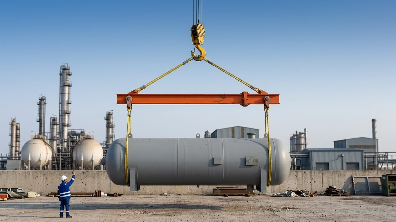
Hoists are often hung from building steel, pipe-rack beams or module frames, using beam clamps, trolleys or slings round the beam. That structure was designed for its own job, not for your lift. Before it is used, someone competent must be satisfied that it can carry the extra load in the direction it will be applied, together with whatever it already carries.
This chapter shows the basic checks so that a lift planner can recognise when a beam is plainly adequate, when it is marginal, and when it is not suitable at all. The final word on existing structure belongs to a structural engineer who knows the design loads already on it.
1. The design point load
The load on the beam is more than the weight lifted:
- The load itself and all rigging below the hoist.
- The hoist, trolley or beam clamp.
- A dynamic allowance for hoisting and lowering. Manual chain hoists are slow and smooth; powered hoists and runway beams are designed with dynamic factors from the crane standards (Chapter 18). A factor of around 1.15–1.25 is common for simple checks; use what your procedure or the engineer specifies.
Example. A 2.0 t load on a 50 kg chain hoist, with a dynamic allowance of 1.15: P = (2.0 + 0.05) × 1.15 = 2.36 t = 23.1 kN.
2. Bending, shear and deflection of a simply supported beam
Point load P at distance a from one support, span L, b = L − a:
M = P × a × b ÷ L (largest under the load; P × L ÷ 4 at midspan)
Bending stress σ = M ÷ Wel (elastic section modulus)
Midspan deflection δ = P × L³ ÷ (48 × E × I) (for a central load)
Shear: reactions P × b ÷ L and P × a ÷ L; web shear stress ≈ V ÷ (depth × web thickness)
Worked example
The 23.1 kN load hangs at midspan of a 5.0 m beam, a 305 × 165 UB at 40 kg/m in S275 steel. Approximate section properties: I ≈ 8,500 cm⁴, Wel ≈ 561 cm³ (strong axis), web 6.0 mm, depth 303 mm.
- M = 23.1 × 5.0 ÷ 4 = 28.9 kN·m; σ = 28.9 × 10⁶ ÷ 561 × 10³ = 51.5 MPa.
- The beam’s own weight adds wL²/8 = 0.395 × 5² ÷ 8 = 1.2 kN·m, which is small here.
- Shear: V = 11.6 kN; τ ≈ 11,600 ÷ (303 × 6.0) = 6.4 MPa, negligible.
- Deflection: δ = 23,100 × 5,000³ ÷ (48 × 210,000 × 8.50 × 10⁷) = 3.4 mm, about span ÷ 1,480.
In isolation, 51.5 MPa is well within what this beam can carry if it is laterally restrained. But the beam already carries a floor, pipework or equipment. Its spare capacity is the difference between its design capacity and its existing load, which only the design records or an engineer can tell you. The lift load may be small, or it may be the last straw.
If the load hangs off-centre at 1.5 m from a support: M = 23.1 × 1.5 × 3.5 ÷ 5.0 = 24.3 kN·m. Midspan is always the worst position for bending under a single load, so a check at midspan covers a trolley that can run along the beam.
3. Side pull: the weak axis
An I-beam is many times stiffer and stronger about its strong axis than its weak axis. For this section the weak-axis modulus is only about 93 cm³, roughly one sixth of the strong-axis value. Any sideways component of the pull, from drifting (Chapter 11), from a hoist that is not under the load, or from a load swinging, bends the beam the weak way.
Example. The same 2.36 t pull, 12° out of vertical, has a horizontal component of 2.36 × sin 12° = 0.49 t (4.8 kN). At midspan:
- Weak-axis moment = 4.8 × 5.0 ÷ 4 = 6.0 kN·m.
- If the whole section resists it: σ = 6.0 × 10⁶ ÷ 92.6 × 10³ = 65 MPa, already more than the stress from the vertical load.
- If the top flange is held by the floor and only the bottom flange resists (165 mm × 10.2 mm, W = 10.2 × 165² ÷ 6 = 46.3 cm³): σ = 130 MPa, plus twisting at the clamp.
A small angle has done more harm than the whole vertical load. This is why many beam clamp and trolley makers do not permit any side pull, and others permit only a small angle at a reduced rating. If a lift needs an angled pull, use an attachment point designed for it.
4. Beam clamps and trolleys
- Fit. The clamp or trolley must suit the flange width and thickness within the maker’s range. Adjust the trolley side plates so the wheels sit correctly on the flange; too much clearance lets it twist and run off.
- Rated load. The rated load applies to a vertical pull centred under the clamp. A clamp at the end of a cantilever or on a tapered flange needs the maker’s approval.
- Wheel loads and local flange bending. A four-wheel trolley carrying 2.36 t (including its own weight) puts about 0.59 t on each wheel near the flange tip. On a thin flange that local bending, not the overall beam bending, can govern. Runway beams for regular use are designed for this (for example to BS EN 1993-6); for a temporary trolley on existing steel, check the maker’s minimum flange thickness for the load.
- End stops. A trolley on an open-ended beam needs end stops that cannot be removed by accident.
5. Slings round beams and other lifting points
- A sling choked or wrapped round a beam must be protected from the flange edges (Chapter 4). The beam is loaded where the sling sits; check that position, not just the midspan.
- Never pass a sling round a beam where it can slide along the flange towards a support or a splice; the geometry and load share will change.
- Welded lifting lugs on structure need a design (Chapter 5), approval from the asset owner, a hot-work permit and inspection of the weld, and must be marked with their rated load and direction. Lugs left from a previous job are not known to be safe.
- Never lift from pipework, valves, cable trays, handrails, ladders, conduit, or the bracing members of a structure, unless an engineer has checked them for that purpose.
6. What you need to know before using structure
- The member size, grade and condition (corrosion, damage, holes, previous modifications).
- The span and how the ends are supported (simply supported, continuous, cantilever).
- What the member already carries, and what it was designed for.
- Whether it is restrained against twisting and sideways buckling where the load is applied.
- The magnitude and direction of the lift load at each position, including drifting and side pull.
- Whether the connections at each end can take the extra reaction.
Record the result as a marked, rated lifting point in the plan. If you cannot get these answers, choose another method: a gantry, a portable frame, a crane from outside, or a designed temporary beam.
6a. Worked example: a monorail runway beam for a 3 t hoist
A new runway beam is planned over a pump bay: span 6.0 m between supports, a 3.0 t electric hoist and trolley weighing 0.15 t, and a dynamic allowance of 1.25 for a powered hoist. The design point load is P = (3.0 + 0.15) × 1.25 = 3.94 t = 38.6 kN, taken at midspan.
- Bending: M = 38.6 × 6.0 ÷ 4 = 57.9 kN·m. With an allowable bending stress of, say, 165 MPa for a fully restrained beam, Wel ≥ 57.9 × 10⁶ ÷ 165 = 351 cm³.
- Deflection: runway beams are usually limited to a small fraction of the span so the trolley does not run uphill; limits in the range of span ÷ 500 to span ÷ 750 are common, depending on the standard. For span ÷ 600 (10 mm): I ≥ P × L³ ÷ (48 × E × δ) = 38,600 × 6,000³ ÷ (48 × 210,000 × 10) = 8,270 cm⁴.
- The 305 × 165 UB at 40 kg/m (Wel ≈ 561 cm³, I ≈ 8,500 cm⁴) passes bending easily but deflection only just: stiffness governs, not strength. That is typical of runway beams.
- Still to check: lateral-torsional buckling (a runway beam is often unrestrained along its length, which can reduce the allowable bending stress considerably), local flange bending under the trolley wheels, the end stops, the supports and their connections, and fatigue if the hoist is used often.
A permanent runway beam is lifting equipment in its own right: it needs a design to the relevant standard, a proof load test, its safe working load marked on it and periodic thorough examination.
6b. Temporary beams across openings
A beam laid across a roof hatch, a floor opening or two trestles to hang a hoist is a temporary lifting point. Check it as above, then make sure it cannot move: the beam must bear fully on its supports (with packing to spread the load on concrete or grating), be prevented from rolling over and from sliding off, and the supports themselves must carry the reactions. Mark it with its rated load and remove it when the job is finished.
Approval. Whoever owns the structure (the plant owner, the building owner or the module fabricator) should approve any temporary lifting point on it, in writing, as part of the lift plan. Their engineer can confirm the existing loads and any restrictions, such as members that must not be welded to or drilled.
7. Common mistakes
- Checking the lift load alone and ignoring what the beam already carries.
- Using a beam clamp for drifting or angled pulls.
- Hanging a hoist from a secondary member, a bracing angle or a purlin that is not designed for point loads.
- Forgetting the hoist and trolley weight and the dynamic allowance.
- Fitting a trolley to the wrong flange width, or with worn wheels.
8. Self-check questions
1. A 15 kN load hangs at midspan of a 4.0 m beam with Wel = 300 cm³. What is the bending stress?
M = 15 × 4.0 ÷ 4 = 15 kN·m; σ = 15 × 10⁶ ÷ 300 × 10³ = 50 MPa.
2. The same load at 1.0 m from one support: what is M?
M = 15 × 1.0 × 3.0 ÷ 4.0 = 11.25 kN·m.
3. Why is a 10° side pull so damaging to an I-beam?
The sideways component bends the beam about its weak axis, which may have one sixth or less of the strong-axis modulus, and often only one flange resists it. A small force produces a large stress and twisting.
4. A trolley with four wheels carries a 3 t load and weighs 0.1 t. With a dynamic allowance of 1.15, what is the load per wheel?
(3.0 + 0.1) × 1.15 ÷ 4 = 0.89 t per wheel.
5. What is the most important unknown when hanging a hoist from existing steel?
What the member already carries compared with its design capacity. Only design records or a structural engineer can tell you how much spare capacity it has.
General guidance only. It does not replace the manufacturer's data, the applicable standards or the judgement of a competent person.
References
Technical references consulted for this chapter. The text and worked examples are original to LiftPlan Pro.
- BS EN 1993-1-1 and AISC 360 (design of steel members); BS EN 1993-6 (crane-supporting structures and runway beams).
- BS EN 13155 Non-fixed load lifting attachments (including beam clamps and lifting beams).
- ASME B30.16 Overhead Underhung and Stationary Hoists; ASME B30.21 Lever Hoists; BS EN 13157 Hand-powered lifting equipment.
All 18 chapters
- Load weight and centre of gravity: the two numbers every lift depends on
- Two-leg bridles: unequal legs, offset centre of gravity and lift points at different heights
- Three- and four-leg bridles: how the load really shares between the legs
- Sling selection: sling types, choke and basket hitches, and the D/d ratio
- Rigging hardware: shackles, hooks, eyebolts and wire rope terminations
- Spreader bars and lifting beams: forces, stability and design basis
- Mobile crane capacity: reading the chart, net load, utilisation and reeving
- Outrigger loads and crane mats: from crane reactions to ground pressure
- Tandem lifts, upending and tailing: sharing a load between two cranes
- Wind on cranes and suspended loads: pressure, sail area and limits
- Drifting loads: moving a suspended load between two hoists
- Snatch blocks, winches and anchors: line pull, block loads and anchor design
- Lifting from structure: beams, trolleys, beam clamps and temporary lifting points
- Jacking, skidding and rolling: friction, push forces, support reactions and cribbing
- Side boom pipelayers: pipe weight, load overhang, tipping and lowering-in
- Forklifts: load centre, load moment, attachments and slung loads
- Load securing for road transport: friction, blocking, lashing and tipping to EN 12195-1
- Dynamic loads: hoisting factors, shock loading, snatch lifts and load swing