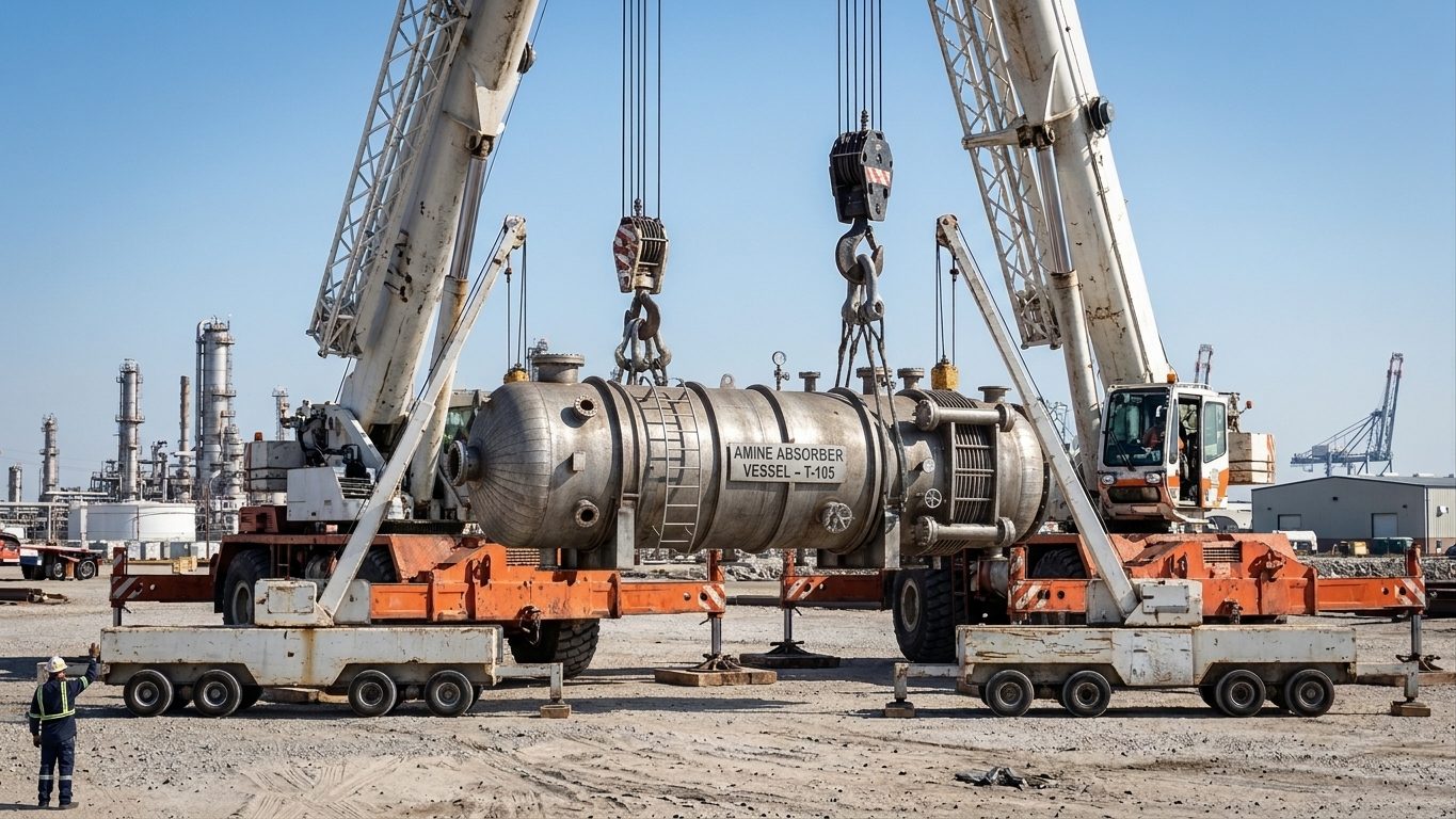
Lifting with two cranes, or two hooks, makes the load statically sensitive. Each crane’s share depends on geometry that changes as the load moves. Small errors in hook position, hoist speed or radius move load from one crane to the other. Multiple-crane lifts should be treated as critical lifts with an engineered plan.
1. Static load share
With both hoist lines plumb, each crane carries a share of the total load in proportion to the horizontal distance from the other lift point to the CoG:
Load on crane A = W × xB ÷ (xA + xB) where xA, xB are the horizontal distances from the CoG to the lift points of cranes A and B
Add each crane’s own rigging below its hook to its share before checking it against that crane’s chart.
2. Upending a vessel: lead and tail cranes
A vertical vessel is often delivered lying down. A lead (main) crane lifts at the top lugs or trunnions and a tail crane holds the base, keeping it off the ground while the vessel is raised to vertical. The tail crane then releases and the lead crane carries the full weight.
Example, at the start (horizontal). A 60 t vessel, 30 m long, with its CoG 12 m from the base. The lead lugs are at the top (30 m from the base) and the tail lug is at the base.
- Lead crane = 60 × 12 ÷ 30 = 24 t
- Tail crane = 60 × 18 ÷ 30 = 36 t
Note that the tail crane starts with the larger share. During upending the shares change. Where the lugs are offset from the vessel axis, as most are, the horizontal distances change at different rates as the vessel rotates. The tail load generally falls and the lead load rises until, at vertical, the lead crane carries everything. Calculate the shares at several angles (for example 0°, 30°, 60° and 80°), using the horizontal distances from the CoG to each lug at each angle, and size both cranes for their worst case.
- The lead crane must also have the capacity for 100% of the load, plus its rigging, at the final radius.
- The tail crane usually has to travel, luff or slew to keep its hoist line plumb while the base moves towards the lead crane. Plan its path and ground support.
- Tail rigging and lugs see a changing load direction. Design the tailing lug for the resultant in every position, and for the moment it is released.
3. Derating and control
- Many procedures limit each crane in a multiple-crane lift to around 75% of its chart capacity (some use 80%). This allows for load transfer from out-of-plumb lines, unequal hoisting speeds and CoG uncertainty.
- Keep hoist lines plumb throughout. A line a few degrees out of plumb side-loads the boom, which the chart does not cover, and shifts load between cranes.
- Use one lift supervisor and one signaller in charge, with a dedicated radio channel. Operators move one function at a time, slowly, on command.
- Use load monitoring on both cranes (rated capacity indicators, plus load cells where the share is sensitive). Set stop criteria in the plan, for example “stop if either crane exceeds X t”.
- An equaliser beam or sheave between two hooks lifting one point fixes the share at 50/50. Remember its own weight.
4. Alternatives
A single larger crane, a lifting frame that lets one crane upend the item with a tilt-up hinge or tailing frame, or a gantry or jacking system may be simpler and safer than a two-crane lift. Weigh up the extra mobilisation cost against the added risk of a tandem lift.
5. Upending: how the tail load changes
When a horizontal vessel is upended, the lead crane lifts the top (head) end at trunnions or a top lug while the tail crane holds the base clear of the ground. Keep both hoist lines vertical, and the share at any angle follows from the horizontal distances between the lines of action and the CoG, exactly as for a beam on two supports:
Tail load = W × (xh − xc) ÷ (xh − xt) Lead load = W − tail load
For a point a distance s along the axis from the base and r off the axis (r positive on the upper side when the vessel lies flat), its horizontal position at upending angle α is s cos α − r sin α.
Example. A 60 t vessel, trunnions 28 m from the base, CoG on the axis 12 m from the base, tail lug 1.2 m off the axis. Lying flat, the tail carries 60 × 16 ÷ 28 = 34.3 t and the lead 25.7 t.
| Angle | Tail load, lug on upper side (t) | Tail load, lug on underside (t) |
|---|---|---|
| 0° | 34.3 | 34.3 |
| 30° | 33.5 | 35.2 |
| 45° | 32.9 | 35.8 |
| 60° | 31.9 | 37.0 |
| 75° | 29.6 | 40.8 |
| 80° | 27.6 | 45.3 |
| 84.3° | about 24 | 60 (all the load) |
| 90° | 0 | unstable before this |
With the lug on the side that is uppermost when the vessel lies flat, the tail load falls steadily and reaches zero when the vessel hangs vertically from the lead crane. With the lug on the underside, the lug swings under the vessel as it rises. The CoG passes over the tail lug when tan α = 12 ÷ 1.2 = 10, at 84.3°. At that point the tail carries the whole 60 t, the lead crane carries nothing, and any further rotation makes the vessel tip over the tail lug and swing towards the lead crane. Lug position and orientation must be part of the lift design, not left to the fabricator.
Following the base
As the vessel rises, the horizontal distance between the lead hook and the tail lug shrinks from 28 m to about 1 m. To keep both lines vertical, the tail crane must travel or slew towards the lead crane, or the lead crane must boom in and travel, or both. Plan the path: the crane that travels with load must have a chart for pick-and-carry (or a travel duty) and the ground along its route must be checked for the track pressures it will impose. Mark the route on the ground and mark the radius limits for each crane.
6. Sensitivity of a two-crane lift
A tandem lift on a stiff load is sensitive to small errors that do not matter for one crane.
- Tilt. If a load with its CoG a height z above the lift points tilts by φ, the vertical shares change by about ΔV = W × z × tan φ ÷ L, where L is the distance between the lift points. A 50 t load with z = 2 m, tilted 3°, lift points 10 m apart: ΔV = 50 × 2 × 0.0524 ÷ 10 = 0.52 t, transferred to the lower end. On a tall module the effect is much larger.
- Out of plumb. A hoist line 2° out of plumb on a 30 t share puts a side load of 30 × tan 2° = 1.05 t on the boom tip. If the boom’s design side load is 2% of a 40 t rating (0.8 t), that small error is already over it. Keep both lines plumb; a spotter at 90° to each boom watches for it.
- Hoist speed. If one crane hoists faster than the other, the load tilts and its share moves to the faster crane. Hoist in small steps, in turn if necessary, keeping the load level by eye or by a level indicator on the load.
Load cells or the cranes’ load indicators, read by one person in charge, are the best control. Set a limit for each crane (for example its planned share plus a margin) at which all motion stops.
7. Planning and control
- A written lift plan by a competent person, reviewed and approved, covering the load shares at every stage, crane configurations and duties, radius changes, travel routes, ground, rigging, wind limits and communications.
- One person in overall charge, normally the appointed person or lift supervisor, giving all commands. Each crane has its own signaller who repeats only that person’s instructions.
- Cranes of similar size and speed where possible; each operating at a reduced duty, commonly no more than 75–80% of its chart capacity, or as the plan’s analysis justifies.
- A pre-lift briefing with every person involved, including what each stop signal means and who can give it.
- A trial lift, raised just clear, held while the shares, level and plumb are checked.
- No slewing or travel by both cranes at once unless the plan shows how the motions are co-ordinated.
8. Worked example: checking both cranes
A 42 t pipe rack module (weighed, including its lifting lugs) is lifted by two cranes from lugs 2.0 m and 14.0 m from the west end. The CoG is 7.4 m from the west end. Each crane has its own rigging: 0.9 t on the west crane and 0.7 t on the east crane, and each hook block weighs 0.8 t. The plan limits each crane to 75% of its chart capacity.
- Lift points 12.0 m apart; CoG 5.4 m from the west lug and 6.6 m from the east lug.
- West share: 42 × 6.6 ÷ 12.0 = 23.1 t; east share: 42 × 5.4 ÷ 12.0 = 18.9 t.
- Gross on the west crane: 23.1 + 0.9 + 0.8 = 24.8 t, so its chart capacity at the worst radius must be at least 24.8 ÷ 0.75 = 33.1 t.
- Gross on the east crane: 18.9 + 0.7 + 0.8 = 20.4 t, needing at least 20.4 ÷ 0.75 = 27.2 t.
Now allow for the effects in Section 6. If the module is 4 m tall with its CoG 2.5 m above the lugs, a 2° tilt moves about 42 × 2.5 × tan 2° ÷ 12 = 0.31 t onto the lower crane. That is within the 25% margin here, but a weight that is only calculated (not weighed) or a CoG with a wide tolerance can use up the margin quickly. State the tolerance you have assumed, and set the load-indicator stop values for each crane from the calculated share plus that tolerance.
9. Common mistakes
- Assuming the shares stay constant during upending. They change with the angle, and the tail share can rise sharply.
- Fitting the tail lug on the wrong side, so the CoG passes over it before the vessel is vertical.
- Forgetting the tail crane’s travel, so its line is dragged out of plumb as the base moves.
- Using the rigging weights only once, at the start; they move with the cranes as the load turns.
- Letting each crane operator decide when to hoist.
10. Self-check questions
1. A 40 t beam is lifted by two cranes at points 2 m and 8 m from one end; the CoG is 4.5 m from that end. What does each crane carry?
Span between lift points 6 m; CoG 2.5 m from the first. Crane at 2 m: 40 × 3.5 ÷ 6 = 23.3 t; crane at 8 m: 40 × 2.5 ÷ 6 = 16.7 t.
2. For the 60 t vessel with the lug on the upper side, what does the lead crane carry at 60°?
60 − 31.9 = 28.1 t.
3. A vessel’s CoG is 10 m from the base and its tail lug is 0.8 m off the axis on the underside. At what angle does it become unstable?
tan α = 10 ÷ 0.8 = 12.5, so α = 85.4°.
4. A 25 t share on a hoist line 3° out of plumb: what side load does it put on the boom?
25 × tan 3° = 1.31 t.
5. Why is a rolling block sometimes used at the tail during upending?
A tail rigged to two lugs through a rolling block keeps the two lug loads equal as the vessel turns, so neither lug is overloaded by small geometric changes. The design must still check the total tail load at every angle.
General guidance only. It does not replace the manufacturer's data, the applicable standards or the judgement of a competent person.
References
Technical references consulted for this chapter. The text and worked examples are original to LiftPlan Pro.
- J. Keith Anderson, Rigging Engineering Calculations (Industrial Training International).
- Rigging Handbook, 2nd edition (Bechtel Equipment Operations, 2002).
- ASME B30.5 Mobile and Locomotive Cranes; BS EN 13000 Mobile cranes; BS 7121 Code of practice for safe use of cranes.
All 18 chapters
- Load weight and centre of gravity: the two numbers every lift depends on
- Two-leg bridles: unequal legs, offset centre of gravity and lift points at different heights
- Three- and four-leg bridles: how the load really shares between the legs
- Sling selection: sling types, choke and basket hitches, and the D/d ratio
- Rigging hardware: shackles, hooks, eyebolts and wire rope terminations
- Spreader bars and lifting beams: forces, stability and design basis
- Mobile crane capacity: reading the chart, net load, utilisation and reeving
- Outrigger loads and crane mats: from crane reactions to ground pressure
- Tandem lifts, upending and tailing: sharing a load between two cranes
- Wind on cranes and suspended loads: pressure, sail area and limits
- Drifting loads: moving a suspended load between two hoists
- Snatch blocks, winches and anchors: line pull, block loads and anchor design
- Lifting from structure: beams, trolleys, beam clamps and temporary lifting points
- Jacking, skidding and rolling: friction, push forces, support reactions and cribbing
- Side boom pipelayers: pipe weight, load overhang, tipping and lowering-in
- Forklifts: load centre, load moment, attachments and slung loads
- Load securing for road transport: friction, blocking, lashing and tipping to EN 12195-1
- Dynamic loads: hoisting factors, shock loading, snatch lifts and load swing