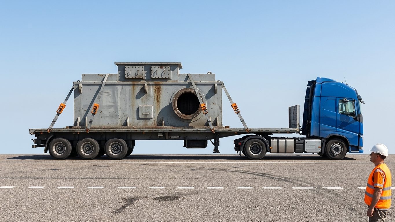
Heavy lift and rigging work does not end when the load is set down on a trailer. Under braking, cornering and acceleration a load tries to keep moving, and the securing arrangement must hold it. BS EN 12195-1:2010 sets the design accelerations and the calculation methods for road transport. This chapter explains the principles and the main calculations. For a compliance calculation use the standard itself or the LiftPlan Pro lashing calculator, which applies its full method and safety factors.
1. The forces to restrain
The standard expresses the design forces as accelerations, as a fraction of g, applied to the load’s mass:
| Direction (road transport) | Coefficient | Force on a 10 t load |
|---|---|---|
| Forward (braking) | cx = 0.8 | 8 t (78.5 kN) |
| Rearward | cx = 0.5 | 5 t |
| Sideways | cy = 0.5 | 5 t |
| Vertical (weight acting down) | cz = 1.0 | 10 t |
2. Friction
Friction between the load and the bed resists μ × m × g × cz in any direction. The friction factor depends on both surfaces and their condition: clean, dry wood on wood or plywood is often around 0.4–0.5; smooth steel on steel can be as low as 0.1–0.2; anti-slip mats commonly give about 0.6. The standard tabulates values to use; anything wet, icy, oily or dusty is lower. Friction is never enough on its own for a heavy load, but it reduces what the lashings or blocking must provide:
Force still to be restrained = (c − μ × cz) × m × g in each direction
Example. A 12 t machine on steel tracks standing on a timber deck, μ = 0.4. Forward: (0.8 − 0.4) × 12 = 4.8 t to restrain. Sideways and rearward: (0.5 − 0.4) × 12 = 1.2 t. The forward direction governs.
3. Blocking
Blocking (the headboard, stanchions, chocks or wedges bolted to the bed) holds the load directly. It needs no friction from lashings and is the most effective restraint for the forward direction. The blocking must be rated for the force it takes: in the example, a headboard against which the machine sits must take 4.8 t. Check the headboard rating on the vehicle (often given as a percentage of payload) and make sure the load bears on the headboard over a sufficient area, not on a point.
4. Top-over (frictional) lashing
A top-over lashing passes over the load and is tensioned to its standard tension force (STF, on the label in daN). It holds by pressing the load onto the bed and increasing friction. Each lashing adds a pressing force of 2 × FT × sin α (the tension acts on both sides). The number needed is approximately:
n ≥ (c − μ × cz) × m × g × fs ÷ (2 × μ × FT × sin α)
FT = tension in the lashing (the STF), α = vertical angle of the lashing, fs = safety factor in EN 12195-1 (1.1; 1.25 in the forward direction)
Example. A 4 t crate, μ = 0.3, webbing lashings with STF = 400 daN (4.0 kN) at α = 70°. Each lashing adds 2 × 0.3 × 4.0 × sin 70° = 2.26 kN of friction.
- Sideways: (0.5 − 0.3) × 4 × 9.81 × 1.1 ÷ 2.26 = 3.8, so 4 lashings.
- Forward: (0.8 − 0.3) × 4 × 9.81 × 1.25 ÷ 2.26 = 10.9, so 11 lashings.
Eleven straps on a 4 t crate is impractical. The answer is to block the crate against the headboard for the forward direction and use top-over lashings for sideways and rearward. Top-over lashing works best with high friction (use anti-slip mats), steep lashing angles and good tensioners; at shallow angles or low friction it does very little.
5. Direct lashing
A direct lashing (chain, wire rope or webbing) runs from a lashing point on the load to one on the vehicle and restrains the load by its own lashing capacity (LC). Its useful component in a given direction depends on the vertical angle α and the horizontal angle β (measured in plan from the direction of travel). It also presses the load down a little, adding friction. Because a direct lashing must stretch before it takes load, the load can slide slightly, so EN 12195-1 uses a reduced friction for this method (μ × 0.75).
Restraint per lashing, forward: LC × (cos α × cos β + μd × sin α) sideways: LC × (cos α × sin β + μd × sin α)
Required: Σ restraint ≥ (c − μd × cz) × m × g, with μd = 0.75 μ. (Simplified to show the principle; the standard’s full method also applies its safety factor.)
Example. The 12 t machine, μ = 0.4 (so μd = 0.3), four chains with LC = 10,000 daN (100 kN), each at α = 40° and β = 30°, two pulling forward and two rearward.
- Forward requirement: (0.8 − 0.3) × 12 × 9.81 = 58.9 kN. Each forward chain: 100 × (0.766 × 0.866 + 0.3 × 0.643) = 85.6 kN; two give 171 kN. Adequate.
- Sideways requirement: (0.5 − 0.3) × 117.7 = 23.5 kN. Each chain gives 100 × (0.766 × 0.5 + 0.193) = 57.6 kN sideways in its direction; two act on each side. Adequate.
The lashing points on both the load and the vehicle must be rated for the chain’s LC in the direction of pull. A strong chain on a weak lashing ring is a weak lashing.
6. Tipping
A tall or narrow load can tip over before it slides. Taking moments about the edge it would tip about, the load is stable sideways if:
b ÷ h ≥ cy ÷ cz (forward: b ÷ h ≥ cx ÷ cz)
b = horizontal distance from the CoG to the tipping edge, h = height of the CoG above the bed
- A transformer 2.0 m wide with its CoG 1.4 m high: b ÷ h = 1.0 ÷ 1.4 = 0.71, more than 0.5: stable sideways.
- A cabinet 0.8 m wide with its CoG 1.2 m high: b ÷ h = 0.4 ÷ 1.2 = 0.33, less than 0.5: it will tip in a hard turn unless lashed or braced against tipping. Tipping must be calculated separately from sliding.
7. Common mistakes
- Relying on the load’s weight to keep it in place. Weight alone does not stop a load sliding under braking.
- Using lashing capacity (LC) in a top-over calculation, or STF in a direct-lashing calculation. Top-over uses the pre-tension (STF); direct uses the capacity (LC).
- Shallow top-over lashings on a low load, which add almost no pressing force.
- Hooking lashings to rope hooks or rub rails not rated as lashing points.
- Forgetting tipping for tall loads, or forgetting that a load on a pallet can slide on the pallet.
- Not re-tensioning after the first few kilometres, when loads settle and webbing stretches.
8. Field checklist
- Load weight and CoG known; bed surface clean and dry; friction value justified (anti-slip mats where needed).
- Forward restraint by blocking where possible; headboard rating checked.
- Lashing method chosen for each direction; number and angles calculated.
- Labels legible: LC and STF on webbing; grade and size on chains; lashing points rated.
- Tipping checked for tall loads; edge protection fitted where lashings pass over edges.
- Re-check tension after the first short distance and at stops.
9. Self-check questions
1. A 6 t load sits on anti-slip mats with μ = 0.6. What forward force must still be restrained?
(0.8 − 0.6) × 6 = 1.2 t (11.8 kN).
2. Sideways, with μ = 0.6, how much must lashings provide?
(0.5 − 0.6) × 6 is negative, so friction alone covers sideways sliding in theory. A minimum number of lashings is still required, and the friction must be assured.
3. Which figure on a webbing label do you use for top-over lashing?
The STF (standard tension force), because top-over lashing works through pre-tension.
4. A load is 1.0 m wide with its CoG 0.9 m above the bed. Is it stable sideways?
b ÷ h = 0.5 ÷ 0.9 = 0.56, just above 0.5: marginally stable. Add lashings against tipping as a precaution.
5. Why is blocking preferred for the forward direction?
The forward design force (0.8 g) is the largest, and frictional lashing becomes impractical. Blocking against the headboard restrains it directly.
General guidance only. It does not replace the manufacturer's data, the applicable standards or the judgement of a competent person.
References
Technical references consulted for this chapter. The text and worked examples are original to LiftPlan Pro.
- BS EN 12195-1:2010 Load restraining on road vehicles: calculation of securing forces; BS EN 12195-2 and -3 (web lashing and lashing chains); IMO/ILO/UNECE Code of Practice for Packing of Cargo Transport Units (CTU Code).
- LOLER 1998 (UK) and its Approved Code of Practice; BS 7121-1 general requirements for lifting operations.
All 18 chapters
- Load weight and centre of gravity: the two numbers every lift depends on
- Two-leg bridles: unequal legs, offset centre of gravity and lift points at different heights
- Three- and four-leg bridles: how the load really shares between the legs
- Sling selection: sling types, choke and basket hitches, and the D/d ratio
- Rigging hardware: shackles, hooks, eyebolts and wire rope terminations
- Spreader bars and lifting beams: forces, stability and design basis
- Mobile crane capacity: reading the chart, net load, utilisation and reeving
- Outrigger loads and crane mats: from crane reactions to ground pressure
- Tandem lifts, upending and tailing: sharing a load between two cranes
- Wind on cranes and suspended loads: pressure, sail area and limits
- Drifting loads: moving a suspended load between two hoists
- Snatch blocks, winches and anchors: line pull, block loads and anchor design
- Lifting from structure: beams, trolleys, beam clamps and temporary lifting points
- Jacking, skidding and rolling: friction, push forces, support reactions and cribbing
- Side boom pipelayers: pipe weight, load overhang, tipping and lowering-in
- Forklifts: load centre, load moment, attachments and slung loads
- Load securing for road transport: friction, blocking, lashing and tipping to EN 12195-1
- Dynamic loads: hoisting factors, shock loading, snatch lifts and load swing