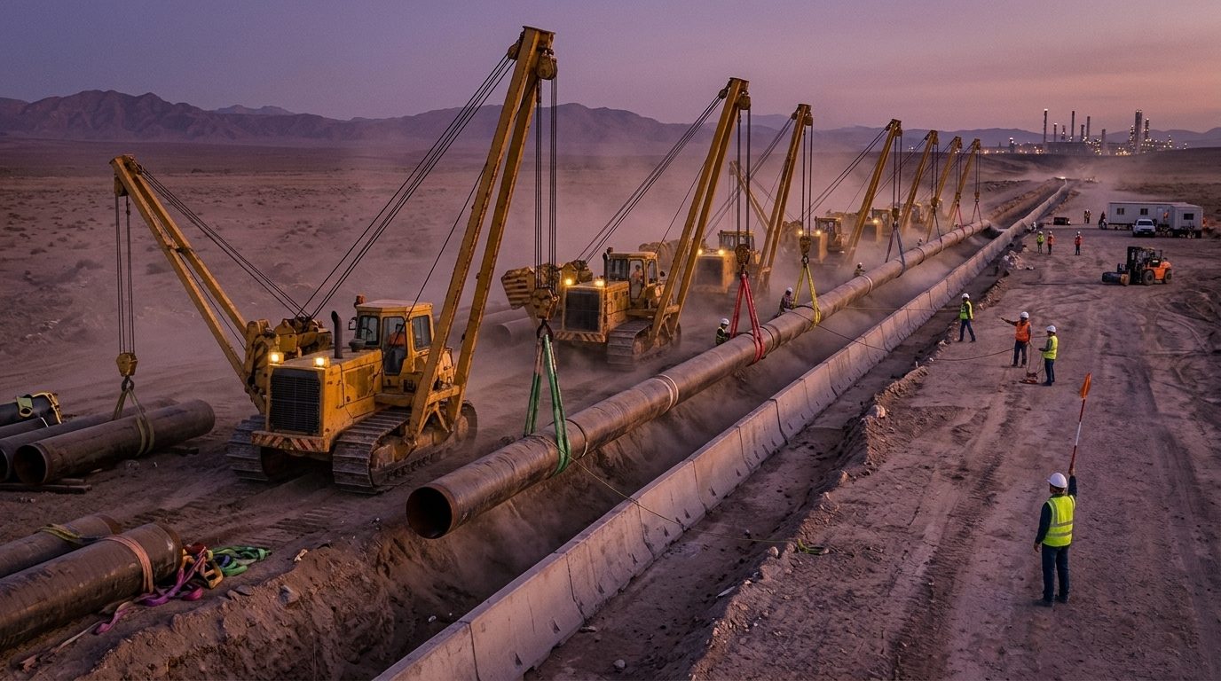
Side boom tractors (pipelayers) lift and lower pipe along pipeline routes, often several machines together on one welded string. They have no outriggers: stability comes from the machine’s weight and its counterweight, which can be extended away from the boom. The lift is limited by tipping about the outer edge of the track on the boom side, so capacity depends heavily on how far the load hangs out from that edge.
1. Pipe weight
Start with the weight per metre, from Chapter 1:
Steel: ws = 7,850 × π × (D − t) × t kg/m Coating: wc = ρc × π ÷ 4 × (Dc² − D²) kg/m
D = steel outside diameter, t = wall, Dc = outside diameter over the coating, ρc = coating density (m in metres)
Example. 36-inch line pipe (914.4 mm OD, 15.9 mm wall) with 75 mm of concrete weight coating at 3,040 kg/m³:
- Steel: 7,850 × π × (0.9144 − 0.0159) × 0.0159 = 352 kg/m.
- Concrete: 3,040 × π ÷ 4 × (1.0644² − 0.9144²) = 709 kg/m. The coating weighs twice as much as the steel.
- Total about 1,061 kg/m: a 24 m double joint weighs about 25.5 t, plus slings or pipe hooks.
Thin anti-corrosion coatings (FBE, 3LPE) add little weight; concrete coating, insulation and water inside the pipe (after a hydrotest, or rain in the trench) add a great deal. Use the coating specification’s density, not a guess.
2. Capacity, overhang and tipping
The machine tips when the load moment about the tipping line equals the restoring moment of the machine and counterweight. Ignoring the boom’s own weight (which the maker includes):
Tipping load Ptip ≈ Mrestoring ÷ overhang Rated capacity = 75% of the tipping load (the basis used in ASME B30.14 and ISO 8813)
Example (illustrative). A 50 t machine whose CoG, with counterweight fully extended, is 1.6 m inboard of the tipping line has a restoring moment of about 80 t·m.
| Load overhang | Tipping load | Rated capacity (75%) |
|---|---|---|
| 1.5 m | 53.3 t | 40.0 t |
| 2.0 m | 40.0 t | 30.0 t |
| 3.0 m | 26.7 t | 20.0 t |
| 4.0 m | 20.0 t | 15.0 t |
| 5.0 m | 16.0 t | 12.0 t |
Doubling the overhang halves the capacity. Always read the maker’s chart for the machine, with the counterweight position stated, and measure the overhang the way the chart defines it (normally horizontally from the tipping line to the hook centreline).
Working on a side slope
If the machine stands on ground sloping down towards the load, its CoG moves towards the tipping line and the hook moves further out. Example: the same machine on a 5° slope, CoG 1.5 m above the ground, hook 6 m up at a 3.0 m overhang on level ground:
- Restoring arm = 1.6 cos 5° − 1.5 sin 5° = 1.46 m, so the restoring moment falls to about 73 t·m.
- Overhang = 3.0 cos 5° + 6.0 sin 5° = 3.51 m.
- Rated capacity = 0.75 × 73 ÷ 3.51 = 15.6 t, against 20.0 t on level ground: a loss of about 22% for a slope that looks gentle.
Most charts assume firm, level ground. Level the working strip, or use the maker’s slope derating, and keep the pipe low while travelling.
3. Sharing a pipe string between machines
For a single joint or double joint lifted at two points, each machine carries its lever-rule share (Chapter 2). A long welded string is different: it is a continuous beam on several flexible supports, and the shares depend on the lift heights, the spacing and the pipe stiffness.
- As a first estimate, each interior machine carries about the pipe weight over one spacing: w × s. For the coated 36-inch pipe at 18 m spacing, that is 1.06 × 18 ≈ 19.1 t, which is about the rated capacity at 3 m overhang in the example above. The overhang must be kept short.
- The end machines carry more or less than w × s depending on how the string is lifted at the free ends and where it touches down. Lowering-in calculations (or the contractor’s lowering-in procedure for that pipe size) give the actual values.
- If one machine lifts higher than its neighbours, it takes more load. Machines must lift and lower together, on one person’s signal.
Pipe bending during lowering-in
The string must not be over-stressed between machines. For a quick check, the bending moment over interior supports of a continuous beam with uniform load is of the order of M ≈ w s² ÷ 10. For the example: M = 1.061 × 9.81 × 18² ÷ 10 = 337 kN·m. The steel pipe’s section modulus is about π D² t ÷ 4 = 0.0104 m³, so σ ≈ 32 MPa, well below the yield of line pipe. Larger spacing, thin-walled pipe, cold bends and lifts to different heights increase it. The concrete coating adds weight but is not relied on for strength, and it cracks if the pipe is bent too sharply.
4. Set-back from the trench
A side boom works beside a trench whose wall can collapse under the track load. Keep the track a safe distance from the trench edge. A common guide is at least the depth of the trench, more in loose, wet or sandy soil, or where the spoil is on the same side. The overhang then includes that set-back, which is why the machine size has to be chosen with the trench geometry in mind, not only the pipe weight.
4a. Worked example: lifting a double joint
A 24 m double joint of the coated 36-inch pipe weighs about 25.5 t. Two side booms lift it with belt slings 5 m from each end.
- The slings are symmetrical about the CoG at 12 m, so each machine carries 12.7 t. At a 3.0 m overhang (rated 20.0 t in the illustrative chart) each machine is at 64%.
- If one sling slides 1 m towards the middle (to 18 m from the first end), the lift points are 13 m apart and the CoG is 7 m from one and 6 m from the other: the shares become 11.75 t and 13.7 t. The nearer machine now works at 69%. Mark the sling positions on the pipe and keep the slings from sliding on the coating.
- Each 5 m overhanging end bends the pipe like a cantilever: M = w L² ÷ 2 = 1.061 × 9.81 × 5² ÷ 2 = 130 kN·m, which is small for this pipe, but much longer overhangs on smaller pipe can kink it or crack the concrete coating.
Travelling with pipe
When the machine travels with a pipe on the hook, the pipe can swing and the ground is rarely level. Keep the pipe low, the boom as far in as practical, the counterweight extended, and travel slowly in the direction the chart allows. Tag lines on long pipe stop it swinging into people or other machines. Never travel with a pipe over people, vehicles or live services.
Communication. On a long lowering-in spread the machines may be 100 m apart along the trench. Use one signaller with radio contact to every operator, agree the commands in advance, and stop all machines if contact with any one is lost.
5. Common mistakes
- Using the steel weight and forgetting the concrete coating or water in the pipe.
- Measuring the overhang from the boom foot or the machine centre instead of the tipping line.
- Working with the counterweight retracted when the chart assumes it extended.
- Ignoring a side slope, or working on soft ground where the track sinks on the boom side.
- Letting machines lift and lower independently on a pipe string.
- Standing between the machine and the pipe, or in the trench under a suspended pipe.
6. Field checklist
- Pipe weight per metre confirmed for steel, coating and contents.
- Maker’s chart for each machine, with counterweight extended, at the planned overhang including trench set-back.
- Ground level and firm; slope derating applied where needed.
- Machine spacing and lift heights set in the lowering-in plan; one person signalling for all machines.
- Slings, belts or pipe hooks rated and suitable for the coating; cradles or rollers where the pipe must move.
- Exclusion zone: no one between machine and pipe, under the pipe or in the trench during lowering-in.
7. Self-check questions
1. What is the steel weight of 24-inch pipe (610 mm OD) with a 12.7 mm wall?
7,850 × π × (0.610 − 0.0127) × 0.0127 = 187 kg/m.
2. A side boom has a restoring moment of 60 t·m. What is its rated capacity at 2.5 m overhang?
Tipping load = 60 ÷ 2.5 = 24 t; rated = 0.75 × 24 = 18 t.
3. Machines are spaced 15 m apart on pipe weighing 0.8 t/m. Roughly what does each interior machine carry?
0.8 × 15 = 12 t.
4. Why does a side slope towards the load reduce capacity so much?
It moves the machine’s CoG towards the tipping line (less restoring moment) and moves the hook outwards (more overhang). Both effects reduce capacity at once.
5. A trench is 2.5 m deep in firm ground. How far back should the track be, as a first guide?
At least about 2.5 m from the trench edge, and more if the ground is poor or wet. The overhang must include this set-back.
General guidance only. It does not replace the manufacturer's data, the applicable standards or the judgement of a competent person.
References
Technical references consulted for this chapter. The text and worked examples are original to LiftPlan Pro.
- ASME B30.14 Side Boom Tractors; ISO 8813 Lifting capacity of pipelayers and side boom machines.
- Rigging Handbook, 2nd edition (Bechtel Equipment Operations, 2002).
- J. Keith Anderson, Rigging Engineering Calculations (Industrial Training International).
All 18 chapters
- Load weight and centre of gravity: the two numbers every lift depends on
- Two-leg bridles: unequal legs, offset centre of gravity and lift points at different heights
- Three- and four-leg bridles: how the load really shares between the legs
- Sling selection: sling types, choke and basket hitches, and the D/d ratio
- Rigging hardware: shackles, hooks, eyebolts and wire rope terminations
- Spreader bars and lifting beams: forces, stability and design basis
- Mobile crane capacity: reading the chart, net load, utilisation and reeving
- Outrigger loads and crane mats: from crane reactions to ground pressure
- Tandem lifts, upending and tailing: sharing a load between two cranes
- Wind on cranes and suspended loads: pressure, sail area and limits
- Drifting loads: moving a suspended load between two hoists
- Snatch blocks, winches and anchors: line pull, block loads and anchor design
- Lifting from structure: beams, trolleys, beam clamps and temporary lifting points
- Jacking, skidding and rolling: friction, push forces, support reactions and cribbing
- Side boom pipelayers: pipe weight, load overhang, tipping and lowering-in
- Forklifts: load centre, load moment, attachments and slung loads
- Load securing for road transport: friction, blocking, lashing and tipping to EN 12195-1
- Dynamic loads: hoisting factors, shock loading, snatch lifts and load swing