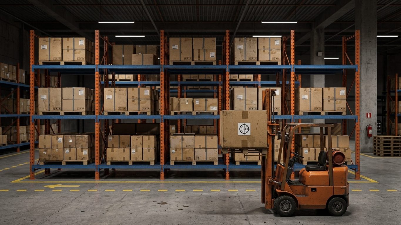
A counterbalanced forklift is a lever. The front axle is the fulcrum; the counterweight and the truck’s own weight sit behind it, and the load sits in front. The truck is rated for a load at a particular distance in front of the forks, the rated load centre, typically 500 mm or 600 mm for medium trucks and more for large ones. Move the load further out and the capacity falls.
1. Capacity at the actual load centre
The load moment about the front axle must not exceed the moment of the rated load at the rated load centre:
Q′ = Q × (A + c) ÷ (A + c′)
Q = rated capacity at rated load centre c; c′ = actual load centre (fork face to the load’s CoG, measured along the forks); A = horizontal distance from the front axle centre to the fork face.
The maker’s capacity plate and load chart take precedence over this formula. Use the formula to understand the chart, to check a load the chart does not show, or when the dimension A is given in the truck data.
Worked example
A truck rated 5.0 t at a 600 mm load centre, with A = 450 mm, must lift a crate 1.8 m deep with its CoG in the middle: c′ = 900 mm.
Q′ = 5.0 × (450 + 600) ÷ (450 + 900) = 5.0 × 1,050 ÷ 1,350 = 3.89 t
If the crate weighs 4.2 t, the truck is overloaded by 8% even though the load is less than the 5 t on the plate. Many tip-overs happen this way: a long or deep load, picked at the fork tips.
Height, tilt and the capacity plate
- Capacity often reduces above a certain lift height, because the mast deflects and the truck’s stability falls. The plate gives the capacity for each lift height.
- Tilting the mast forward with a raised load moves the load centre further out. Tilt forward only with the load just above the place it is set down.
- A truck fitted with a different mast, tyres or attachment must have a capacity plate for that configuration.
2. Attachments
An attachment (side shifter, fork positioner, clamp, rotator, crane jib) adds its own weight in front of the axle and usually pushes the load further forward. Both reduce capacity. With an attachment of weight wa whose CoG is ca in front of the fork face, adding a thickness δ to the load centre:
Q″ = [Q × (A + c) − wa × (A + ca)] ÷ (A + c′ + δ)
Example. The 5.0 t truck with a 200 kg side shifter, CoG 50 mm in front of the fork face, adding 100 mm to the load centre, for a load at 600 mm: Q″ = (5.0 × 1,050 − 0.2 × 500) ÷ (450 + 600 + 100) = 5,150 ÷ 1,150 = 4.48 t. The attachment cost more than half a tonne of capacity. The truck must carry a plate showing the capacity with the attachment fitted.
3. Suspended loads: jibs and hooks
A crane jib or hook attachment lets a forklift lift a load on slings. The load now hangs far in front of the axle and can swing.
Example. The same truck with a 0.3 t jib (CoG 1.0 m from the fork face) and the hook 2.0 m from the fork face:
- Without the jib weight: 5.0 × 1,050 ÷ (450 + 2,000) = 2.14 t.
- With it: (5,250 − 0.3 × 1,450) ÷ 2,450 = 1.97 t, before any allowance for swing.
A swinging load moves its line of action outwards and adds dynamic load. Typical rules for slung loads: only use a jib or hook attachment designed for the truck and shown on its plate; derate as the maker requires; keep the load as low as possible; travel slowly on smooth, level ground; use tag lines; and never hang slings directly from the forks, where they can slide off or be cut.
4. Stability beyond the load chart
- Lateral stability. The truck’s sideways stability is much less than its forward stability. A load off the truck centreline, a turn at speed with the load raised, or a side slope can tip it sideways. Keep the CoG of the load on the centreline and travel with it low.
- Slopes. With a load, drive up and down slopes with the load facing uphill; never turn on a slope.
- Long loads. Pipes, tubulars and steel sections carried crosswise must be balanced side to side and secured against rolling. Wide forks spread and fork extensions must be rated for the load and the truck.
- Ground. Soft ground or a pothole under one front wheel tilts the mast and moves the load outwards.
4a. The stability triangle and turning
A counterbalanced truck stands on two front wheels and a rear axle that pivots at its centre, so it is supported, in effect, at three points: the stability triangle. The combined CoG of truck and load must stay inside that triangle. Raising the load raises the combined CoG; turning, braking and slopes move it sideways or forwards.
In a turn of radius r at speed v, the sideways acceleration is v² ÷ r. The truck starts to tip when that acceleration (as a fraction of g) reaches about b ÷ h, where b is the sideways distance from the combined CoG to the edge of the triangle and h is the height of the combined CoG.
Example. At the position of the combined CoG the triangle edge is 0.45 m to the side. With the load carried low, the combined CoG is 0.8 m high: the truck tips at about 0.45 ÷ 0.8 = 0.56 g. With the load raised and the combined CoG 1.2 m high: about 0.45 ÷ 1.2 = 0.375 g. Turning on a 5 m radius at 15 km/h (4.17 m/s) gives 4.17² ÷ 5 = 3.47 m/s², or 0.35 g: almost at the limit with the load raised, before any bump or slope. This is why trucks overturn sideways in turns, and why loads are carried low and speeds kept down in turns. (Real trucks also have tyre and mast deflection, which reduce the margin further.)
4b. Fork arms and capacity plates
- Fork arms are rated in pairs (or sets) for the truck. Each fork should carry its own rating mark. Remove a fork from service if it is cracked, if wear has reduced the blade or shank thickness to about 90% of the original, if the fork tips differ in height by more than about 3% of the blade length, or if the heel angle has opened. Thorough examination standards (for example ISO 5057) give the detailed limits.
- Fork extensions must be rated, the right size for the forks (normally not longer than about one and a half times the fork blade), and shown on the capacity plate when they change the capacity.
- Capacity plate. If the plate is missing, illegible, or does not show the attachment fitted, do not use the truck until the correct plate is fitted.
4c. Worked example: a pipe bundle off a trailer
A bundle of 12 m long pipes weighing 4.2 t is to be unloaded with the 5.0 t truck (rated at 600 mm, A = 450 mm). The bundle is 0.9 m deep across the forks, so if it sits tight against the fork face its load centre is 450 mm.
- Capacity at 450 mm: the formula gives 5.0 × 1,050 ÷ 900 = 5.83 t, but the plate maximum is 5.0 t. Use 5.0 t; the bundle is at 84%.
- If the bundle is picked 300 mm out from the fork face (because the forks will not go fully under), the load centre is 750 mm: capacity 5.0 × 1,050 ÷ 1,200 = 4.38 t, so the truck is at 96%. Insist on full fork entry.
- The pipes overhang 5.5 m or more each side of the truck. If the CoG is 0.3 m off the truck centreline because the pipe ends are staggered, the sideways margin shrinks: in the stability triangle example, b falls from 0.45 m to 0.15 m and the truck would tip sideways at about 0.15 ÷ 0.8 = 0.19 g even with the load low. Centre the bundle carefully, spread the forks as wide as possible, travel very slowly, and use a banksman to watch the overhanging ends.
- Check the route for slopes, kerbs and potholes. A long overhanging load magnifies every tilt of the truck at its ends.
4d. Two forklifts on one load
Lifting a long load with two forklifts is a tandem lift (Chapter 9) with less forgiving machines: forklifts have no load moment indicators and their operators cannot see each other’s forks well. Avoid it where possible. If it must be done, calculate each truck’s share and load centre, keep each truck well within its capacity (many procedures limit each to around 75%), use one signaller for both, lift and travel at walking pace in a straight line, and never let one truck move while the other is still.
5. Common mistakes
- Reading only the headline capacity on the plate, not the load centre and height it applies to.
- Picking a deep load at the fork tips, so the load centre is far beyond the rated value.
- Fitting an attachment without an updated capacity plate.
- Lifting slung loads from the forks or with a home-made jib.
- Tilting forward with a raised load, or travelling with it high.
6. Field checklist
- Load weight known; load centre measured to the CoG along the forks.
- Capacity at that load centre and lift height checked on the plate or chart, including any attachment.
- Forks spread to suit the load and fully under it; load tight against the fork face or backrest.
- Ground firm and level along the route; slopes and turning points planned.
- For slung loads: approved jib or hook attachment, derated capacity, tag lines, slow travel, exclusion zone.
7. Self-check questions
1. A 3.0 t truck is rated at 500 mm with A = 400 mm. What can it lift at 700 mm?
3.0 × 900 ÷ 1,100 = 2.45 t.
2. A 2.6 t load has its CoG 750 mm from the fork face. Can the truck in question 1 lift it?
Capacity at 750 mm = 3.0 × 900 ÷ 1,150 = 2.35 t. No: the load exceeds it by about 11%.
3. Why does an attachment reduce capacity twice over?
Its own weight sits in front of the axle and uses up load moment, and its thickness pushes the load further forward, increasing the load’s lever arm.
4. Why is the formula Q′ = Q(A + c) ÷ (A + c′) not used to increase capacity for short loads?
At short load centres the limit is usually the truck’s structure, hydraulics or mast, not tipping. The plate capacity is the maximum unless the maker shows a higher value.
5. What is the main extra hazard when a forklift lifts a suspended load?
The load can swing, moving its line of action further out and adding dynamic load, which can tip the truck forward or sideways.
General guidance only. It does not replace the manufacturer's data, the applicable standards or the judgement of a competent person.
References
Technical references consulted for this chapter. The text and worked examples are original to LiftPlan Pro.
- ISO 3691-1 Industrial trucks: safety requirements; ISO 22915 series (stability of industrial trucks); HSE L117 Rider-operated lift trucks.
- LOLER 1998 (UK) and its Approved Code of Practice; BS 7121-1 general requirements for lifting operations.
All 18 chapters
- Load weight and centre of gravity: the two numbers every lift depends on
- Two-leg bridles: unequal legs, offset centre of gravity and lift points at different heights
- Three- and four-leg bridles: how the load really shares between the legs
- Sling selection: sling types, choke and basket hitches, and the D/d ratio
- Rigging hardware: shackles, hooks, eyebolts and wire rope terminations
- Spreader bars and lifting beams: forces, stability and design basis
- Mobile crane capacity: reading the chart, net load, utilisation and reeving
- Outrigger loads and crane mats: from crane reactions to ground pressure
- Tandem lifts, upending and tailing: sharing a load between two cranes
- Wind on cranes and suspended loads: pressure, sail area and limits
- Drifting loads: moving a suspended load between two hoists
- Snatch blocks, winches and anchors: line pull, block loads and anchor design
- Lifting from structure: beams, trolleys, beam clamps and temporary lifting points
- Jacking, skidding and rolling: friction, push forces, support reactions and cribbing
- Side boom pipelayers: pipe weight, load overhang, tipping and lowering-in
- Forklifts: load centre, load moment, attachments and slung loads
- Load securing for road transport: friction, blocking, lashing and tipping to EN 12195-1
- Dynamic loads: hoisting factors, shock loading, snatch lifts and load swing